ADAMS Labs: Cam
Introduction:
This ADAMS Lab will introduce you to the following skills:
- Creating rigid bodies
- Creating splines
- Creating joints and contact conditions
- Setting up and running simulations
- Analyzing results
Problem:
|
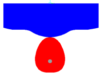
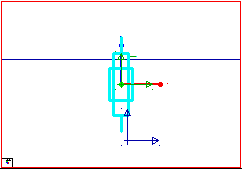
The cam mechanism that will be created, ananlyzed, animated, and ploted in this lab is shown here. |
|
Schematic of the Cam Mechanism: The model contains 3 parts (including ground), 1 revolute joint, 1 translational joint, 1 motion, and several markers.
Procedure:
1.1. Starting ADAMS.
- From the ADAMS product menu,
select ADAMS.
The Run ADAMS dialog box appears. - Select OK.
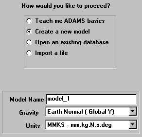
The Welcome to ADAMS dialog box appears as shown in Figure 1. - Under the heading "How
would you like to proceed", select Create a new model.
Verifty that the Gravity text field is set to Earth Normal (-Global Y).
Verify that the Units text field is set to MMKS - mm,kg,N,s,deg.
Select OK.
|
Figure 1. Welcome to ADAMS. |
1.2. Setting up the modeling environment.
- The grid spacing needs to be
reset to a higher resolution for this model.
Go to the Settings pull-down menu at the top of the ADAMS window and select Working Grid... - In the Spacing text
fields, enter 10mm under both X and Y.
Click OK. The spacing between grid points is now set to 10mm. - Click on the Select
icon.

The View Control panel appears in the Toolbox. - Click on the Dynamic Zoom
icon.

Now click and hold with the left mouse button anywhere inside the Modeling window. Move the mouse up to zoom in and move it down to zoom out.
1.3. Making the cam part.
- Click on the parts palette in
the Toolbox with the right mouse button.
The button stack for parts appears. - Click on the Spline icon
 with the left mouse button.
 - In the lower part of the
Toolbox, verify the text field is set to New Part.
Click in the box next to the word Closed to select a closed spline. - Now, click with the left mouse button on each of the 13 points in the table below.
|
Points |
1 |
2 |
3 |
4 |
5 |
6 |
7 |
8 |
9 |
10 |
11 |
12 |
13 |
|
X |
0 |
-50 |
-70 |
-80 |
-70 |
-50 |
0 |
50 |
70 |
80 |
70 |
50 |
0 |
|
Y |
0 |
-30 |
-70 |
-120 |
-160 |
-180 |
-190 |
-180 |
-160 |
-120 |
-70 |
-30 |
0 |
|
Z |
0 |
0 |
0 |
0 |
0 |
0 |
0 |
0 |
0 |
0 |
0 |
0 |
0 |
Note that the first point and the last point have the same coordinates to create a closed spline.
After the 13 points are selected, click the right
mouse button to create the closed spline. An alert box will appear warning you
that the part has no mass. Close the box.
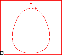
The complete cam part is created, as illustrated in Figure X.
If your part's geometry does not match the illustration, it can be fixed by
clicking and dragging any of the "hot points" (rectangular boxes) to
its proper location.
|
Figure X. Closed spline. |
1.4. Creating a revolute joint.
- Click on the Joint icon
in the Toolbox and select the Joint:Revolute icon
 from the
joints button stack.
 - Verify that the Construction text fields read 1 Location and Normal to Grid.
- Position the cursor over the grid point (0,-130,0) and click once with the left mouse button.
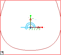
- A joint between the cam part and the ground is created at that location, as illustrated in Figure X.
|
Figure X. Revolute joint |
1.5. Creating the follower part.
The follower part is comprised of two geometric elements: and open spline and a box.
Creating the open spline element.
- Select the Spline icon

- In the lower part of the Toolbox, verify the choice Closed is not selected, since an open spline is to be created.
- Now, click with the left mouse button on each of the 11 points in the table below.
|
Points |
1 |
2 |
3 |
4 |
5 |
6 |
7 |
8 |
9 |
10 |
11 |
|
X |
-250 |
-200 |
-150 |
-100 |
-50 |
0 |
50 |
100 |
150 |
200 |
250 |
|
Y |
50 |
40 |
40 |
30 |
10 |
0 |
10 |
30 |
40 |
40 |
50 |
|
Z |
0 |
0 |
0 |
0 |
0 |
0 |
0 |
0 |
0 |
0 |
0 |
After the 11 points are selected, click once with
the right mouse button to create the open spline. An alert box will appear
warning you that the part has no volume. Close the box.
The open spline is created as shown in Figure X. Again, "hot points"
may be used to modify the spline geometry.
|
Figure X. Open spline. |
Creating the box element.
- Select the Rigid Body: Box
tool
 from the parts button stack.
 - In the New Part pull-down menu, select Add to Part.
- Click on the open spline in the ADAMS window to select the part to add to.
- Now define the corners of the
box.
Position the cursor at the left end of the open spline (-250,50,0). - Click and drag upward and to
the right until the upper right corner of the box is at the coordinates (250,180,0).
Release the mouse button.
The box element is created, as illustrated in Figure X.
|
Figure X. Box element. |
1.6. Adding a Translational Joint.
Now create a translational joint between the follower part and the ground part with the axis of translation aligned in the global y direction.
- Click on the Joint icon
in the Toolbox with the right mouse button.
The joints button stack appears. - Select the Joint:Translational
icon.

- Verify that the Construction text fields are set to 1 Location and Pick Feature.
- Position the cursor over the
grid point (0,160,0) and click once with the left mouse button.
This is where the joint will be located. - Now, move the cursor upalong
the Y axis away from the origin until an arrow pointing straight up
appears.
Make sure the arrow is parallel to the Y axis. This arrow determines the direction of the translational joint.
Click the left mouse button. - A joint between the follower part and the ground is created, as illustrated in Figure X.
|
Figure X. Translational joint. |
1.7. Adding a Curve-Curve Constraint.
- Click on the Joint icon
in the Toolbox and select the Cam (curve-on-curve) contact icon
 from
the joints button stack.
 - Click on the cam part, and
then click on the spline part of the follower part.
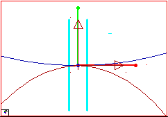
A curve-on-curve contact constraint is created as shown in Figure X.
|
Figure X. Curve-curve contact. |
1.8. Creating a Motion Constraint.
All of the parts have now been created and the constraints added. The next step is to add a rotational motion driver to the revolute joint that specifies a constant cam rotation of one revolution per second.
- Select the Rotational Joint Motion icon from the Toolbox.
- In the Speed text field, which now appears, enter 360d to set the motion displacement to be 360 degrees per second.
- Click on the revolute joint
in the cam part with the left mouse button.
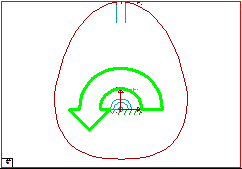
A large motion arrow appears around the revolute joint in the cam part, as shown in Figure X.
|
Figure X. Rotational Joint Motion. |
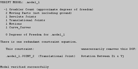
1.9. Verify the model.
The model verification step is one way to find errors in the model definition. ADAMS checks for error conditions such as misaligned joints, unconstrained parts, or massless parts in dynamic systems, and alerts you to other possible problems in the model.
- In the lower right corner of
the modeling window, click on the Information icon
 with the
right mouse button.
The information palette appears. - Click on the Verification
icon.

The Info Window appears, as shown in Figure X. - After seeing that the model has verified successfully, click on the Close button in the upper right corner to close the Information Window.
|
Figure X. Verify model. |
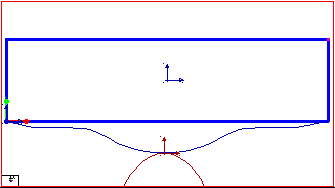
The completed model should appear similar to the picture below:
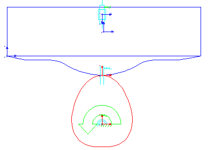
(There is no cmd file available for this problem.)
Model building is now complete.
Set up and run a simulation.
1.10. Setting measures.
- Select the follower part by
clicking on it in the ADAMS Modeling window with the left mouse button .
The part becomes highlighted. - On the Build menu at
the top of the Modeling window, point to Measure, then to Selected
Object, and select New.
The Part Measure dialog box appears. - Select CM Position for the Characteristic text field and select Y for the Component entry to to measure the displacement in the Y direction.
- Click Apply.
A graph window appears. This is where data will be displayed. - Now repeat this procedure, except select CM Velocity for Characteristic.
- Repeat this procedure once
more for CM Acceleration.
A new graph window will appear for each new measure. - After the three graph windows are created, click Cancel to close the Part Measure dialog box.
1.11. Running the simulation.
- Click on the Simulation icon
 in the Toolbox. For End Time, enter 1 and
for Steps, enter 50.
 - Click on the Play icon.

You should see the cam rotate about the pivot and the follower slide along its translational joint.
Corresponding data should be plotted on each graph. - When the simulation ends,
click on the Rewind icon.

1.12. Plotting results.
- In each of the graph windows, a plot corresponding to each of the measures set earlier appears.
- To get a closer look at a
plot, click on a blank area inside the small plot window with the right
mouse button and follow the pull right menu. Select Transfer to Full
Plot.
The ADAMS Plot Window will open, replacing the modeling window. To return to the modeling window, go to the File pull-down menu and select Return to Modeling.
1.13. Saving your Modeling Session.
- Under the File pull-down
menu, select Save Database As...
The Save Database As dialog box appears as shown in Figure X. - In the text field next to File Name, enter the name you wish to give this model, for example, cam.
- Select OK.
An ADAMS Binary File is created.
|
Figure X. Save Database As... |
1.14. Exiting ADAMS.
- Select Exit from the File pull-down menu in the main ADAMS Modeling window.
Congratulations, you have completed ADAMS Lab: Cam.
Did it work?
- Make sure correct units are set to mmks.
- Make sure the revolute joint is in the z direction.
- Make sure translational joint is in the y direction.
- Check dimensions of the part to make sure they are correct.
- Check locations of spline points to make sure they are correct.
- Check orientation of the parts to make sure they are correct.
- Make sure the measures are set correctly.
- Make sure the plot is displaying the correct set of results.
