| Lecture
#24 |
| Much not in text; some in Section 14.5 |
| CURMUDGEON
GENERAL'S WARNING. These "slides"
represent highlights from lecture and are neither
complete nor meant to replace lecture. It is
advised not to use
these as a reliable means to replace missed
lecture material. Do so at risk to healthy
academic performance in 09-105. |
|
| Lecture Outline |
Molecular orbitals (delocalized)
1,3 butadiene example
Excited states
Benzene
Ozone
Particle-in-a-box energies
|
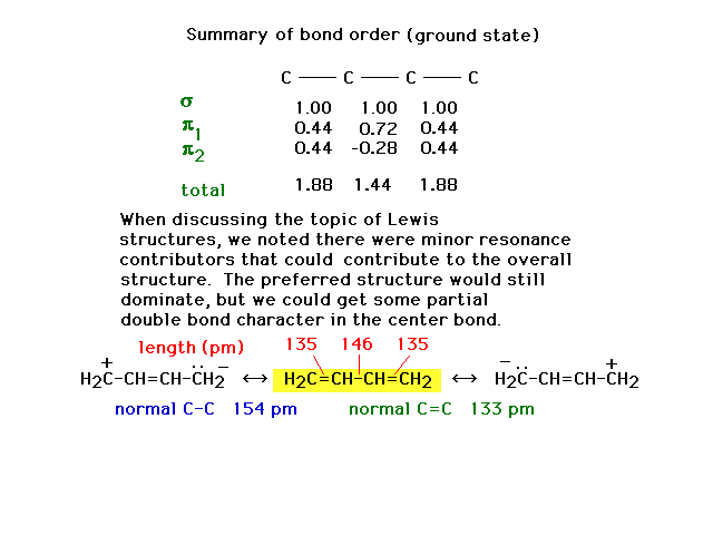
| The difference in the molecule's structure when
molecular orbital theory is used can be accommodated with
resonance Lewis structures that are not what we call
"preferred" structures, but which nevertheless
affect the overall appearance of the molecule. The bonds
are neither pure double bonds nor pure single bonds. |
 |
| Next, we'll consider structural changes in the
molecule when it is in an excited state. |
 |
| Interpretation of the change follows in an
uncomplicated manner. |
 |
| Way back, when we were finishing up Lewis structures,
we used benzene as the prime example of where resonance
entered into play. In the molecular orbital view, the
resonance structures arise from place electrons into
delocalized orbitals constructed from various
combinations of atomic p orbitals. Note that steric
number three at each carbon gives us a trio of sp2 hybrid
atomic orbitals and a pure 2p atomic orbital
perpendicular to their plane. |
 |
| The six 2p atomic orbitals are in position to overlap
in various ways, the most energetically stable being
constructive interference everywhere. This provides a
picture of the first pi molecular orbital. |
 |
| A second combination is shown here in which a couple
of nodes are implied where the orbital amplitude switches
from + to -. |
 |
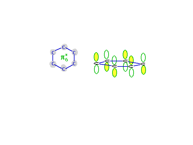
| The highest energy, least stable, molecular orbital
comes from the combination of atomic orbitals that has
the most destructive interference. Wave amplitude between
neighboring carbons is depleted in this combination which
is antibonding everywhere. |
 |
| The six combinations, some of which were not
illustrated, have energies indicated in this diagram. The
construction of the diagram is beyond this course, but
its use is straightforward since a total of six electrons
must be placed...as shown. |
 |
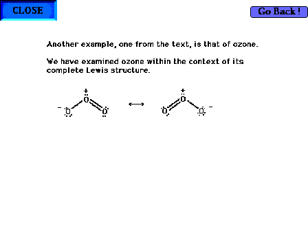
| The ozone molecule's Lewis structure shows that even
the preferred structure in this case indicates resonance
is required for a complete description of the molecule's
valence electrons. Note that a pair of electrons involved
in bonding oxygens is delocalized. But also note that a
"non-bonding", lone pair is also resonating
between both end sites in the Lewis structure. |
 |
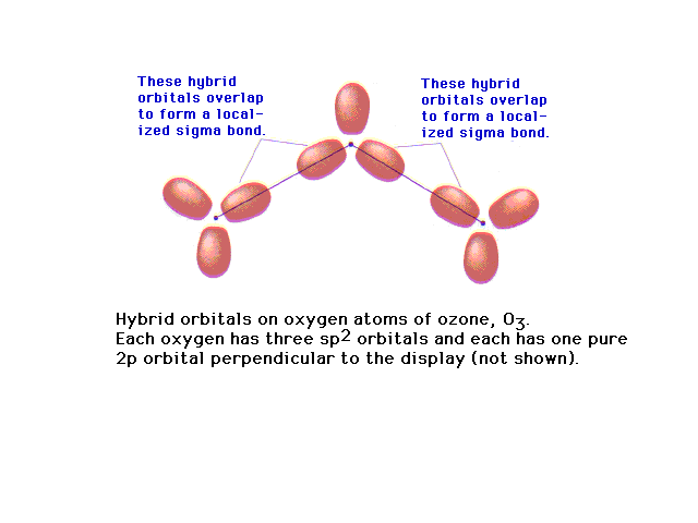
| Of the 18 valence electrons in ozone, two pair are
involved in resonance. The remaining 14 electrons
constitute the sigma bonded framework shown here as
coming from sp2 hybrids at each oxygen (since
each is in an electronic geometry involving three
groups). |
 |
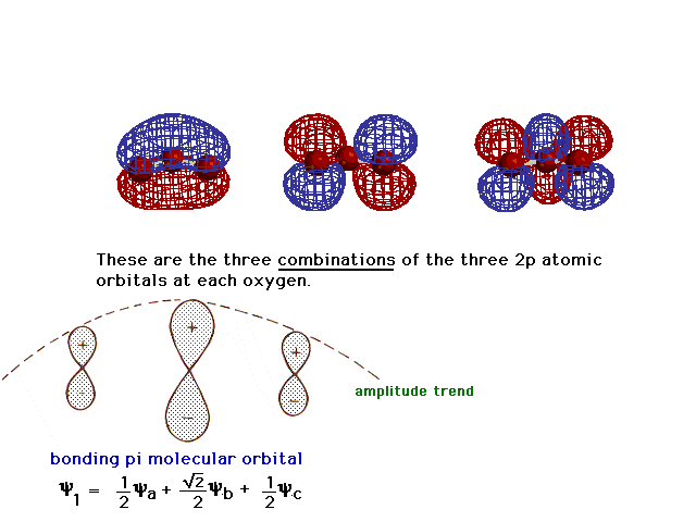
| There is a pure 2p atomic orbital at each oxygen
perpendicular to the plane of the molecule. These lead,
via linear combinations, to three delocalized pi
molecular orbitals. The one involving constructive
interference leading to a bonding molecular orbital is
illustrated at the right. |
 |
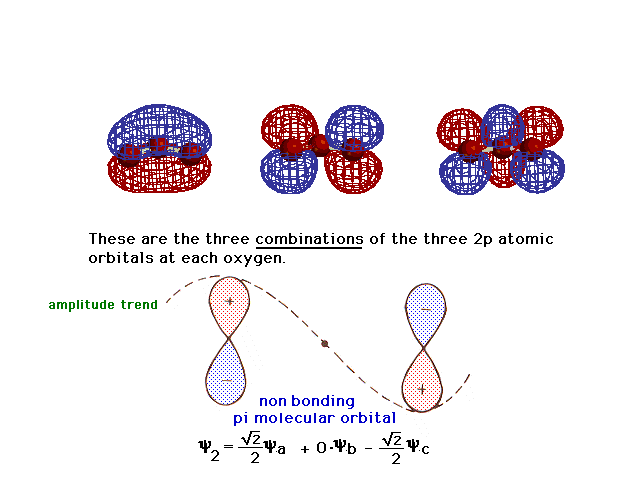
| Here is the second linear combination. |
 |
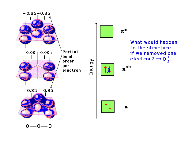
| And the third, the antibonding delocalized molecular
orbital corresponding to the bonding one. You should be
able to figure out the "partial bond order per
electron" for an electron in each of these three
orbitals. |
 |
| The pi molecular orbital energy diagram for ozone
into which are distributed four valence electrons. Two
are in the bonding orbital and yield a bond order of 0.7,
which when added to the sigma bond corresponds to a bond
order of 1.7 between each of the oxygens. The remaining
pair is distributed at each end, corresponding to the
negative charge simultaneously at each end oxygen in the
Lewis structure. |
 |
Changing the electron configuration of non-
bonding orbitals does not affect the structure
significcantly. |
 |
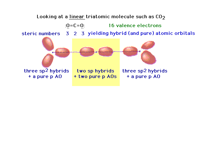
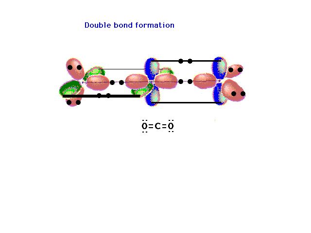
| Another triatomic molecule is carbon dioxide. The
text presentation of this is awkward, so it's completely
re-constructed here following the arguments that should
seem familiar. Here's the underlying framework with the
hybrids on the end oxygens lying in two planes
perpendicular to each other. This arrangement will lead,
in the next slide, to the ready formation of two double
bonds. |
 |
| The pure p orbitals perpendicular to the hybrids
overlap effectively in pairs -- not all three at once --
as shown here. Two pure double bonds arise in this
manner. The placement of all 16 valence electrons is
indicated. |
 |
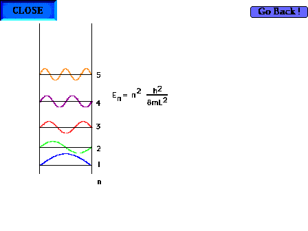
| The particle-in-a-box model can now be profitably
revisited. Showing the first five waves and their
energies. There are, of course, an infinite number of
such possibilites corresponding to shorter and shorter
wavelengths and higher and higher energies. |
 |
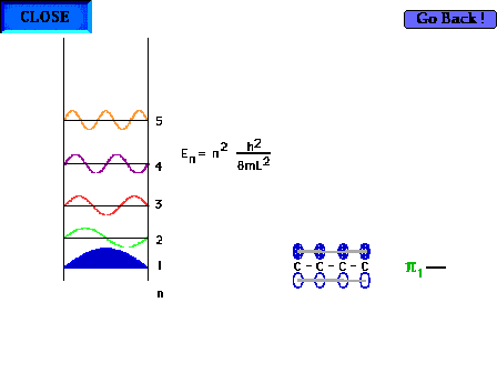
| The shape of the n=1 particle-in-a-box wave function
approximates the appearance of the ground state pi wave
function for the delocalized molecular orbital in 1,3
butadiene for instance. |
 |
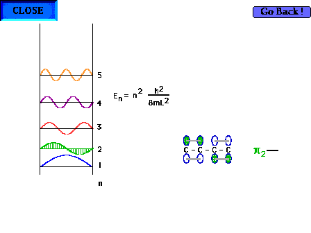
| The shape of the n=2 particle-in-a-box wave function
approximates the appearance of the p2
orbital in a delocalized system. |
 |
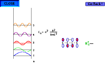
| The shape of the n=3 particle-in-a-box wave function
approximates the appearance of the p*3
delocalized orbital. |
 |
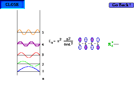
| The shape of the n=4 particle-in-a-box wave function
approximates the appearance of the p*4
delocalized orbital. |
 |
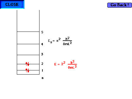
| There are four electrons "free" to
delocalize in the 1,3 butadiene system H2C=CH-CH-CH2 |
 |
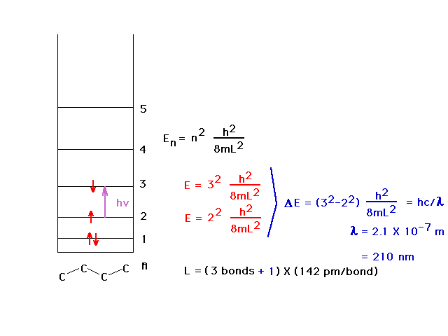
| The average carbon-carbon bondlength (C=C and C-C) is
142 pm and allows calculation of the wavelength of the
absorbed light by using the particle-in-a-box to estimate
the energy levels. The ultraviolet wavelength is 210 nm.
We allow the box to extend beyond the outer nuclei by
another one-half bond at each end. |
 |