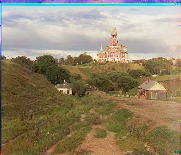
R (303, 185) G (294, 294)
R (89, 7) G (40, 6)
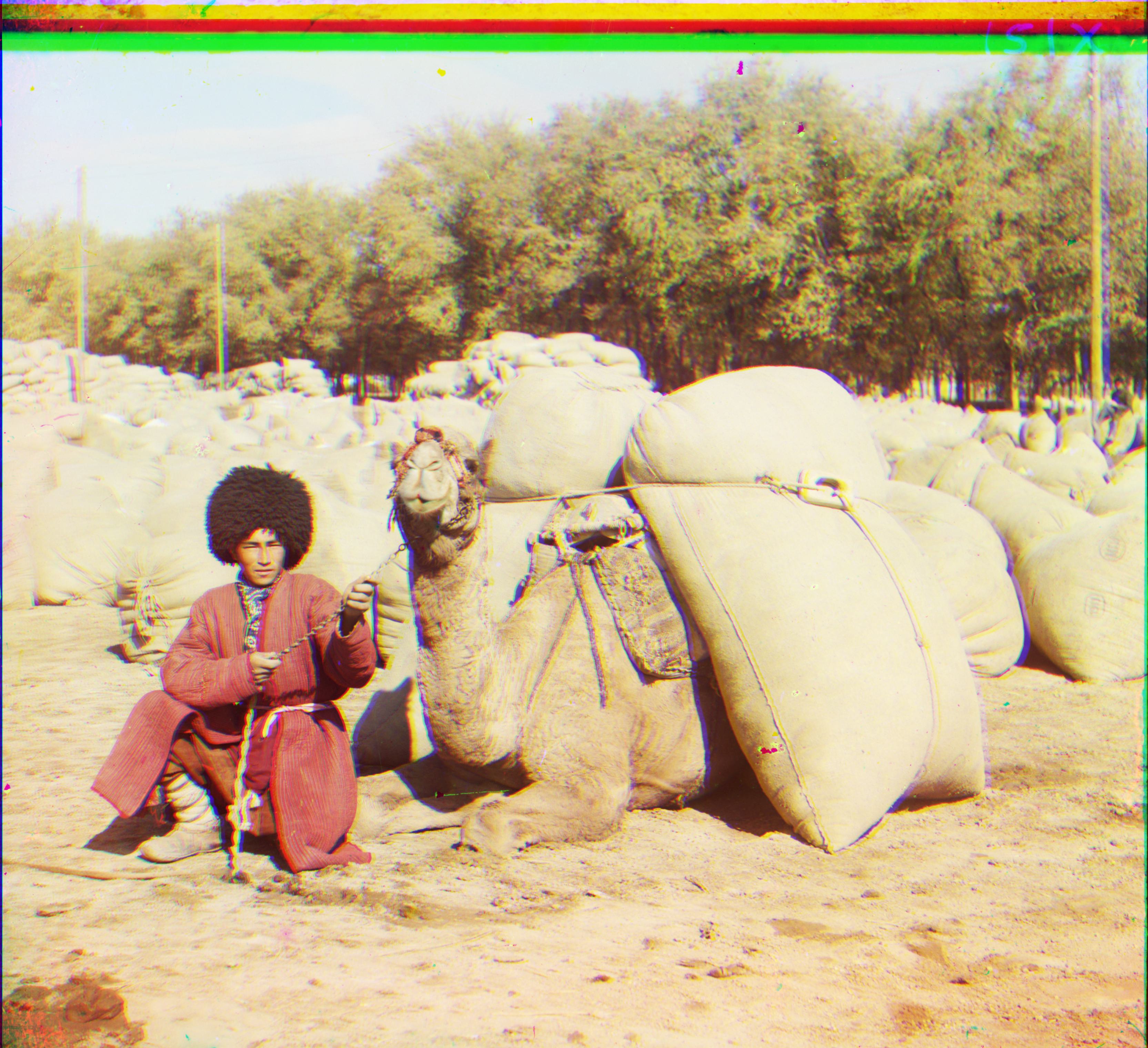
R (114, 8) G (55, 6)
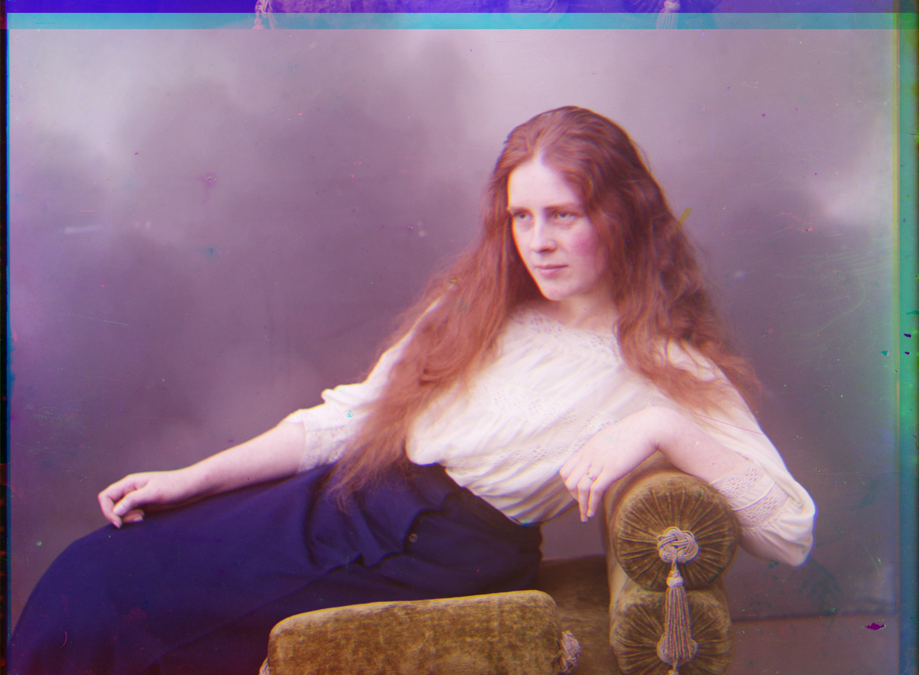
R (111, 1) G (49, 1)
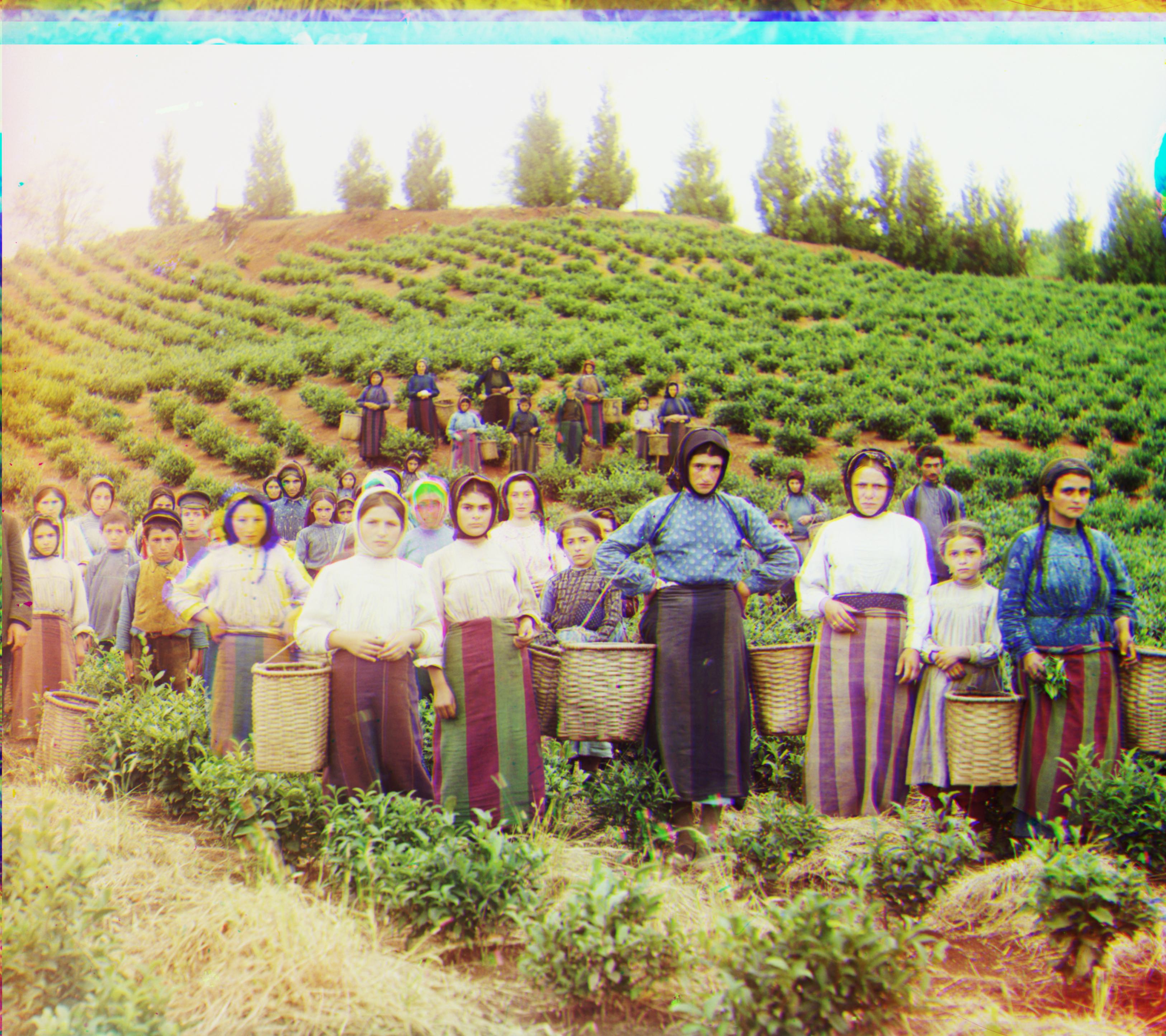
R (124, 5) G (60, 6)
Yiwen Zhao's Project Page
Sergei Mikhailovich Prokudin-Gorskii (1863-1944) traveled across the vast Russian Empire and take color photographs of everything he saw in 1907. He used an amazing technique which record three exposures of every scene onto a glass plate using a red, a green and a blue filter. This plates are envisioned to be integrated to color image by a projector and share with others.
His RGB glass plate negatives, capturing the last years of the Russian Empire, survived and were purchased in 1948 by the Library of Congress. The LoC has recently digitized the negatives and made them available on-line.
Design an algorithm to automatically align the 3 channels.
The simplest inplementation cut the plate and overlaped the three parts, which has an obvious misplacement (or aliasing), calling for further alignment.
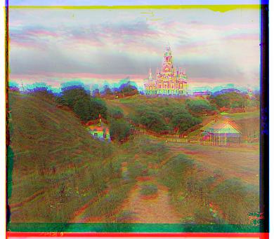
Initially, I used pixels to align the channels.
I use the single scale matching first. It works well in cathedral.jpg, which is probably the most easy sample because it is in compressed format. However, the searching speed for .tif files slows down drastically.
To cut the time cost in 1 minute, I use the pyramid image scale with a flexible structure up to 5 levels, using sk.transform.rescale. The number of levels depends on the input image size.
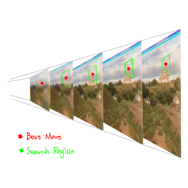
Here lists some of my observations in Prokudin-Gorskii Photo Collection. I use them as basic assumptions to design the algorithm.
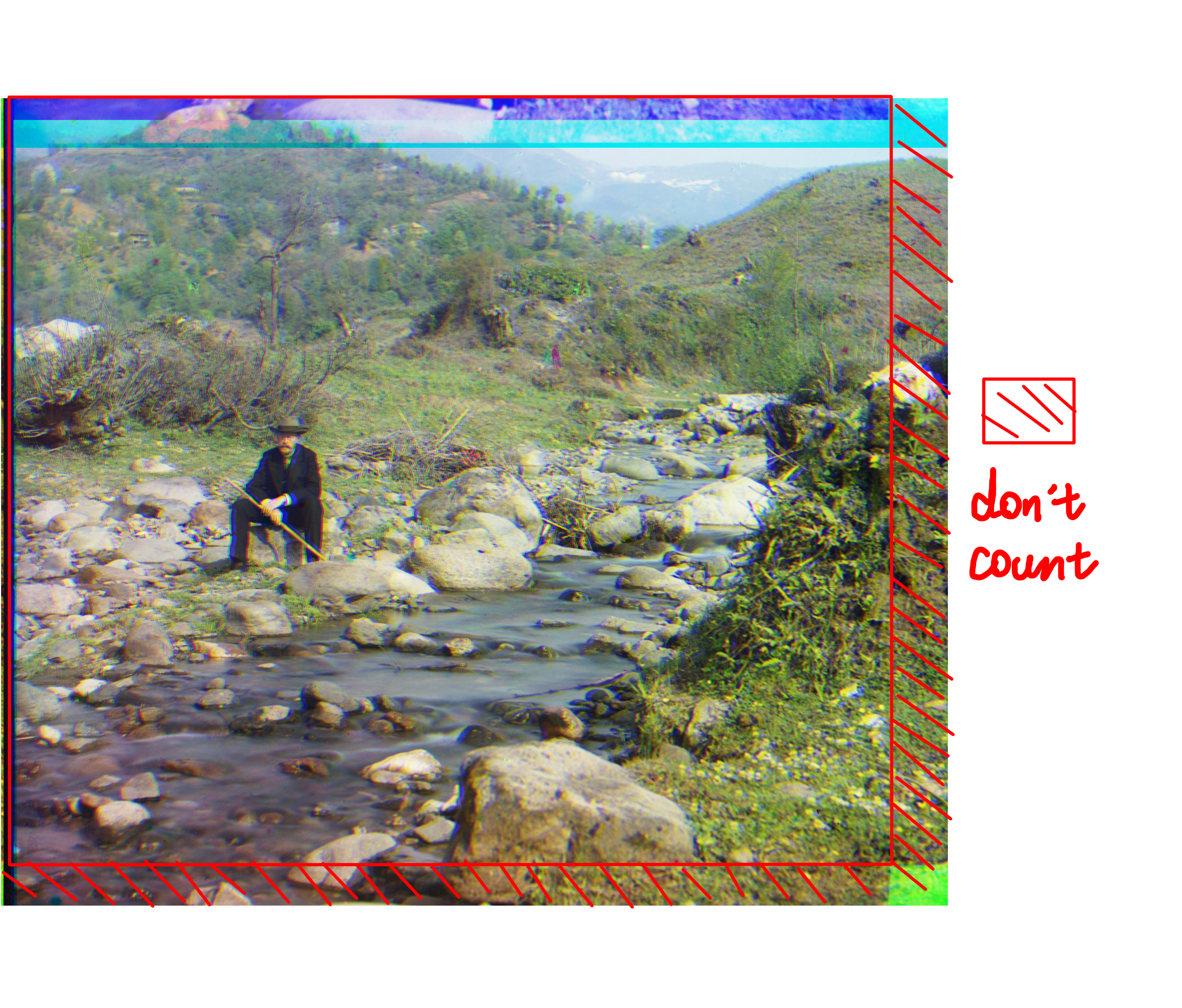
Border is in a dark, frame-like structure. The black and white borders of each channel differ. The inborn mismatching makes these borders ineffectual, even detrimental in alignment. Thus, they should be excised at the outset.
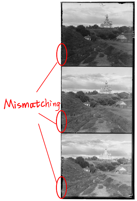
I designed an automatic algorithm to search the border using dark pixel ratio in scan windows.
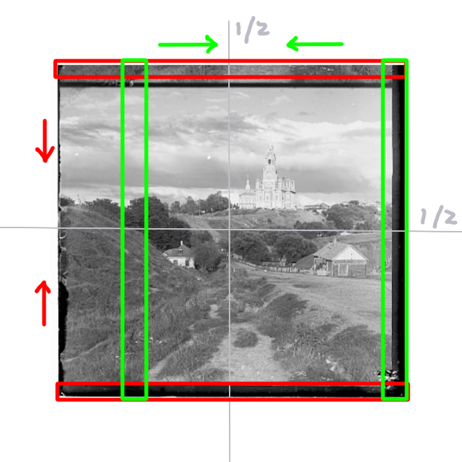
These assumptions highly depend on the Prokudin-Gorskii Photo Collection domain characteristics. In other words, they may not be transferable to other domains, which is a pity.
In some test cases, pixel matching is enough to output a 'OK' result.

R (303, 185) G (294, 294)
R (89, 7) G (40, 6)

R (114, 8) G (55, 6)

R (111, 1) G (49, 1)

R (124, 5) G (60, 6)
I opted for np.roll to move the R and G channels as aligned as they could to the B channel. One thing worth mentioning is that, in the loss calculation, those moved pixels shouldn't be counted in. Say a channel is move up-left, then a small rectangle will appear in the down-right corner, which has no reason to be count.
I chose the NCC loss. It remove the effect of brightness by np.linalg.norm(). For a 2D input, this operation is defined by dividing the input by
Furthermore, due to the np.roll operation, the NCC should be normalized by the number of pixels used for calculating loss. (Only calculating the dot product is ok for inputs in a unanimous size, but not reasonable for inputs in various sizes).
On the contrary, SSD is not suitable to be averaged to each pixel, thus less flexible on various input sizes.
However, there are several hard cases in pixel matching. I think one reason is that they have a large portion of R/G/B color content.
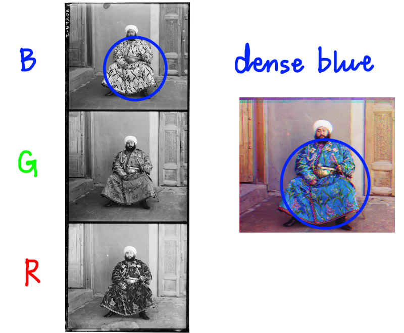
For instance, if a 3-channel red circle is divided into R/G/B grayscale images, the G/B channels might lack significant information while the R channel contains dense pixels, thereby complicating pixel search.
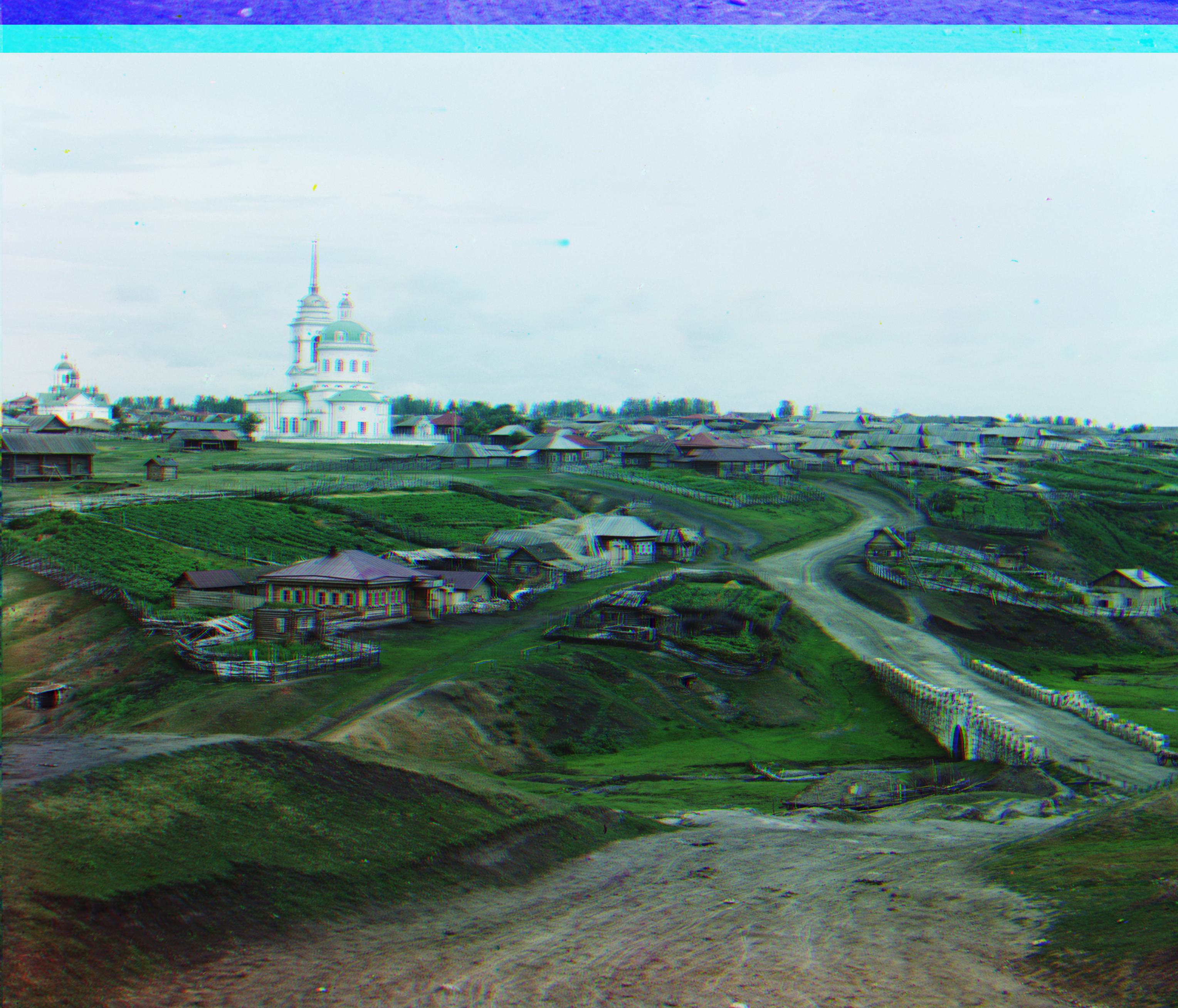
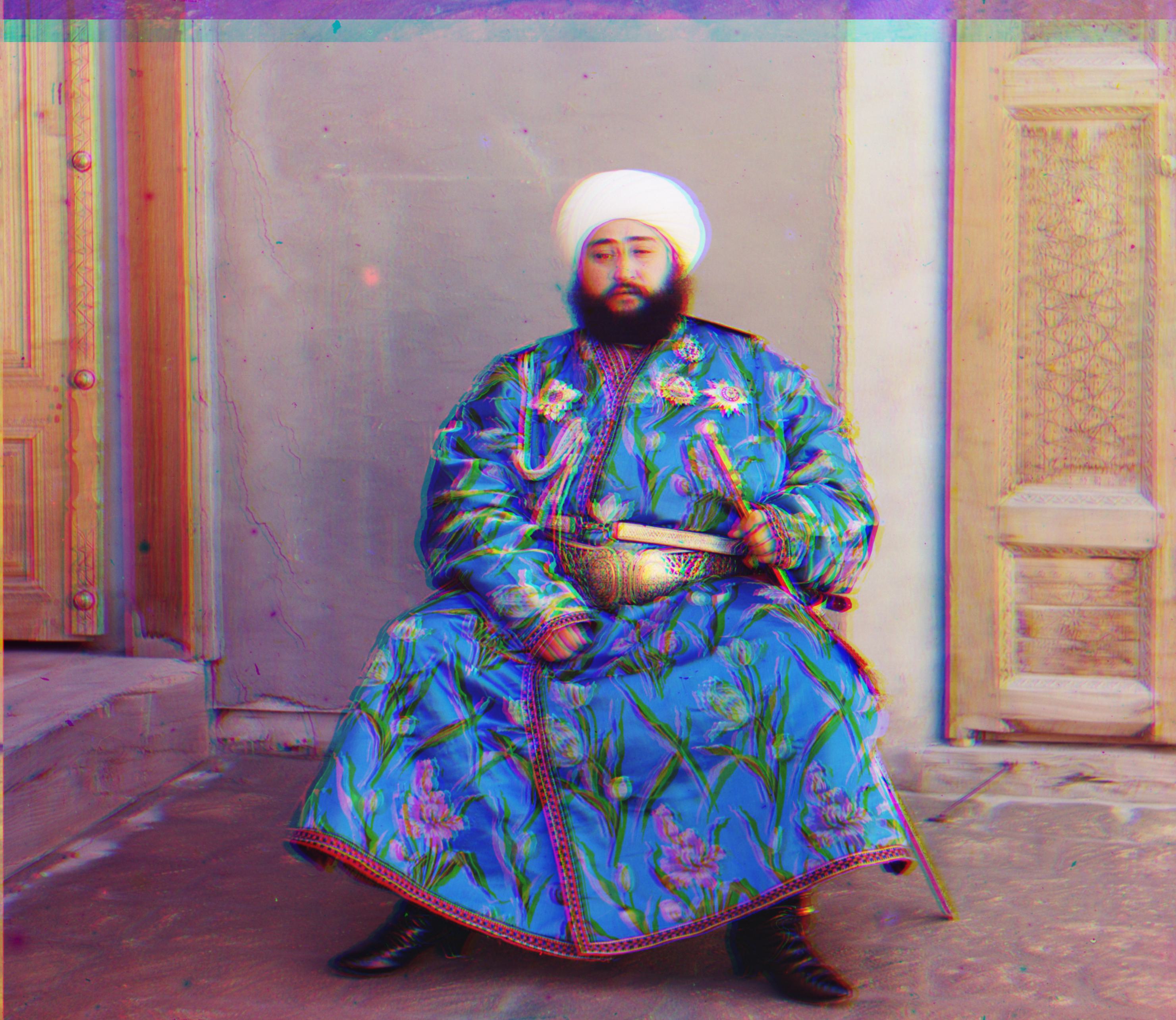
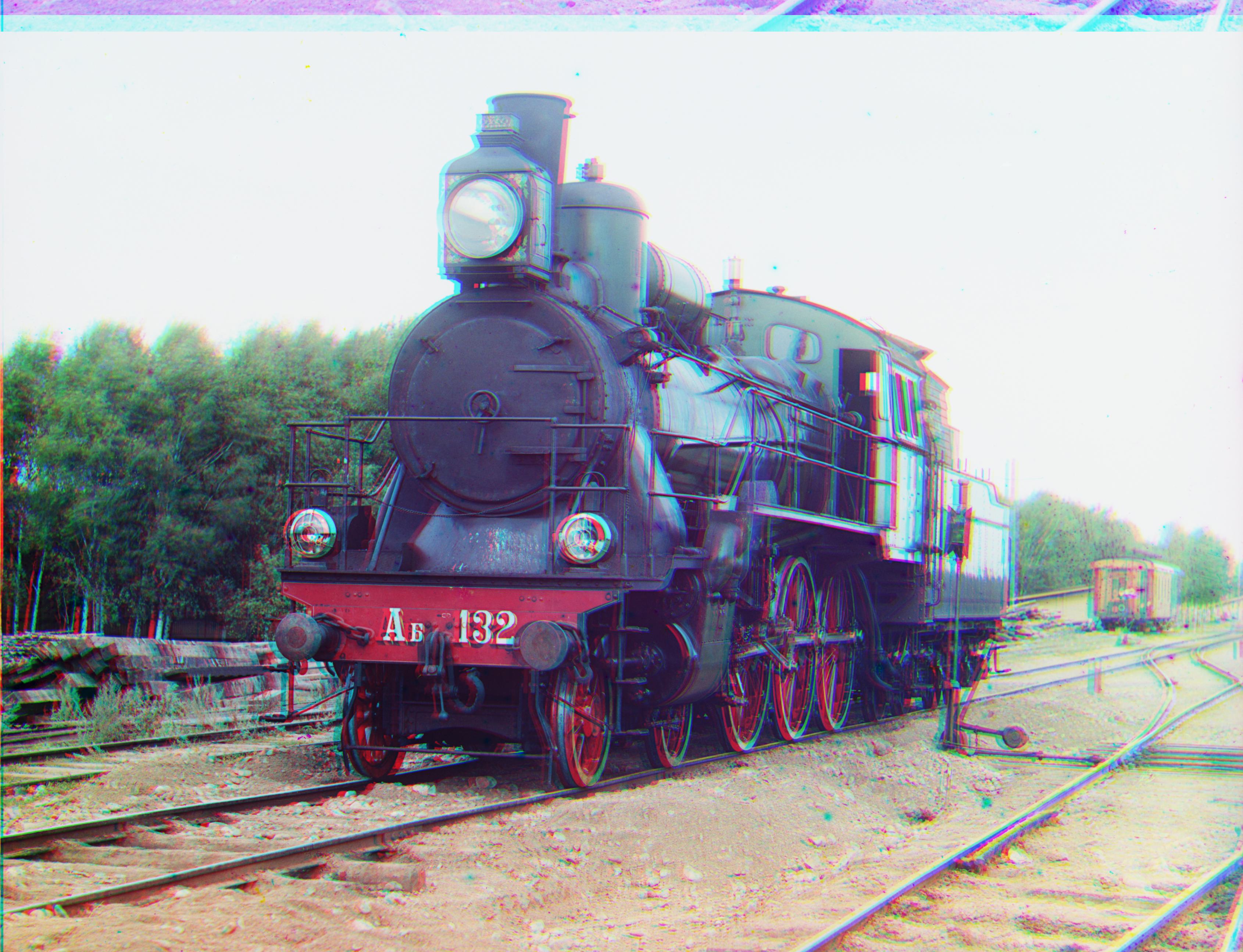
Fortunately, many edge features are shared across channels. I initially employed the Sobel kernel, effective in detecting vertical and horizontal lines. Implementing gradient magnitude notably improved the reconstruction of previous failure cases.
R (160, 373) G (77, 8)
R (173, 10) G (76, 8)
R (111, 4) G (2553, 2509)

R (112, 4) G (54, 5)
R (2374, 1044) G (2230, 1143)
R (137, 7) G (64, 4)
R (0, 251) G (49, 7)
R (106, 10) G (49, 7)
R (2522, 2069) G (2486, 560)
R (86, 9) G (41, 1)
left: Pixel Search -- right: Edge Search
I also tried Canny kernel, but in emir.tif case it even preform worse than pixel search. Althought Canny can detect detailed edges and curves better than Sobel, these details are not shared by all channels. In contrast, Sobel focus on channel-unanimous straight (black) lines, resulting in better outcomes. Consequently, I chose Sobel for edge detection.

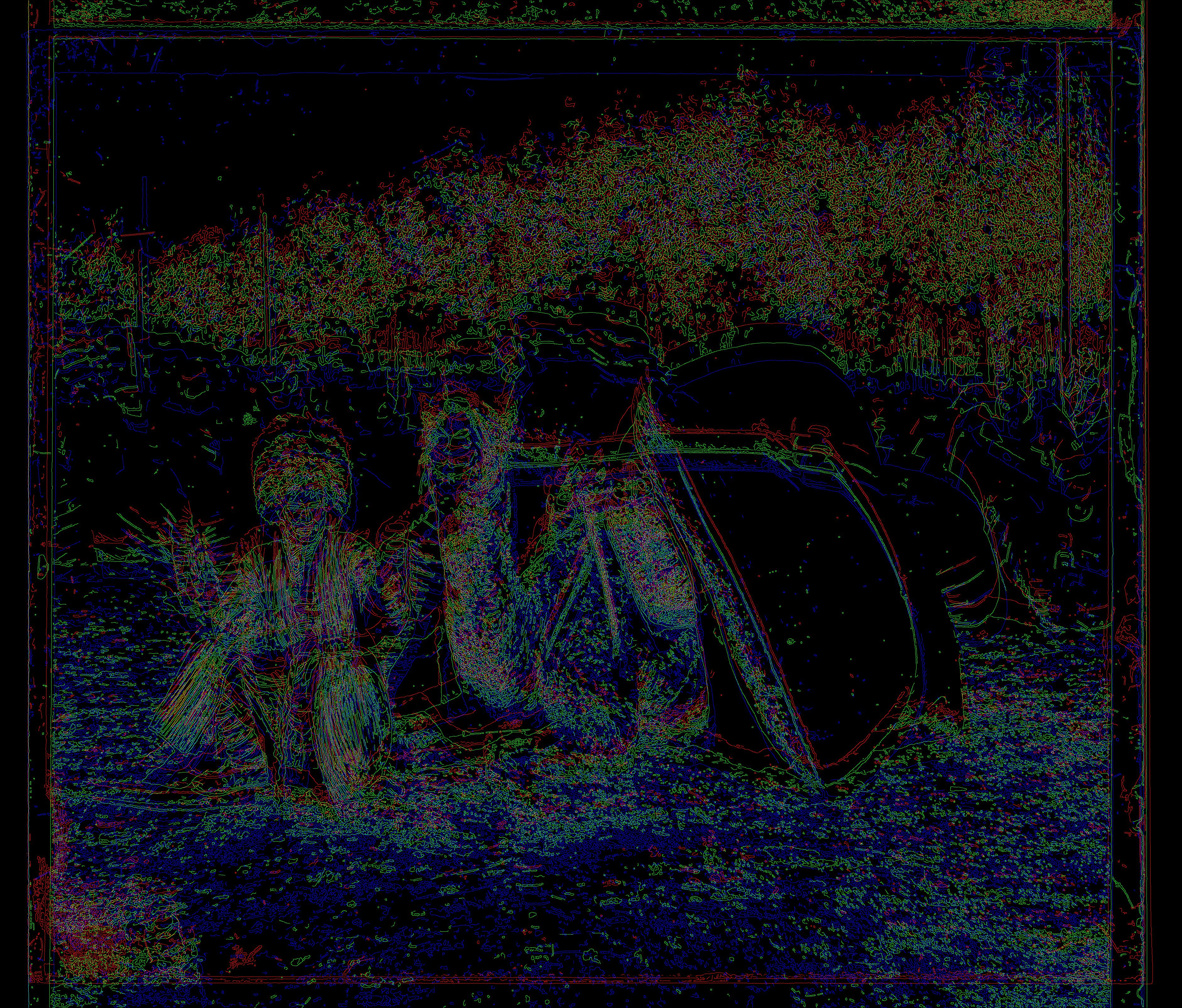
left: Sobel Kernel -- right: Canny Kernel
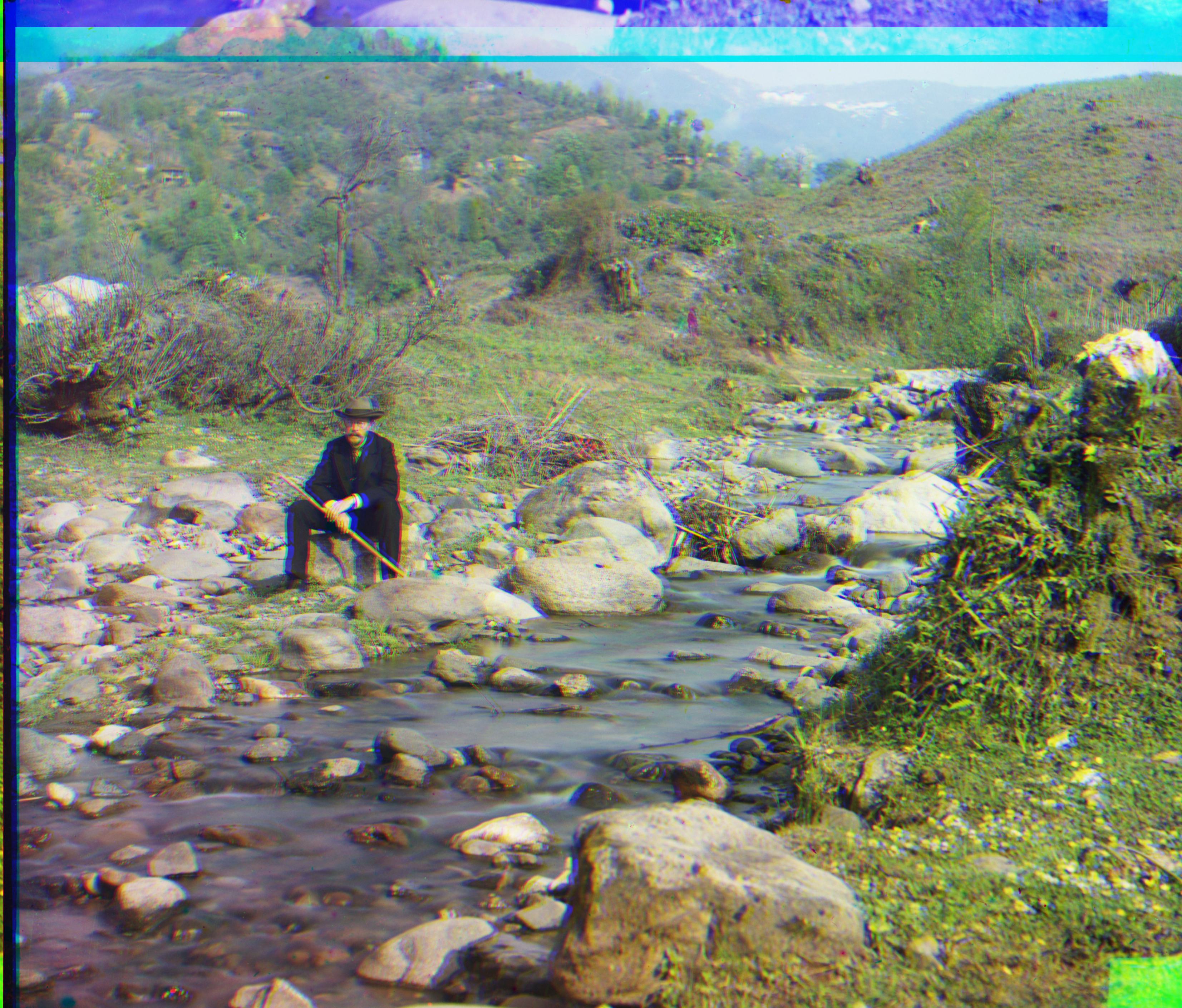
Nonetheless, there is still some visible mismatching between channels. The blue artifacts are obvious here.
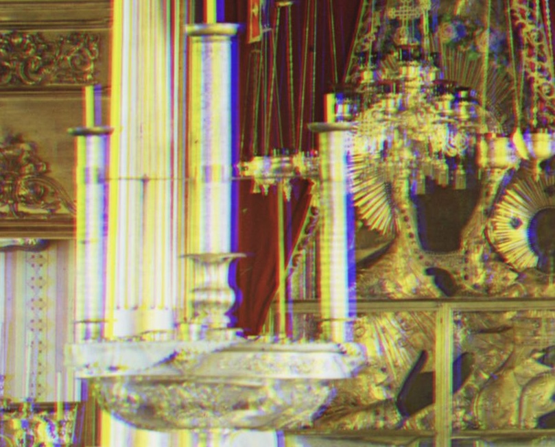
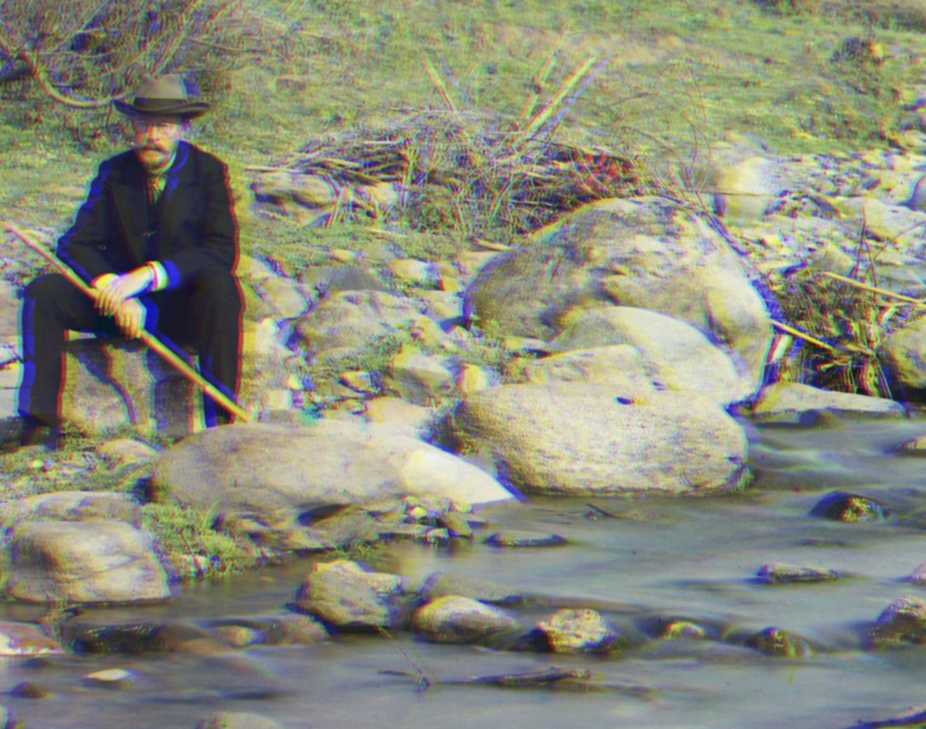
One possible reason is the presence of animals (including humans), flowing water, or other movable objects in the image. As the images from the three channels of different filters were captured sequentially, natural mismatches may occur between these elements.
Another reason is that, after visualization, the edge features are not exactly the same across channels.
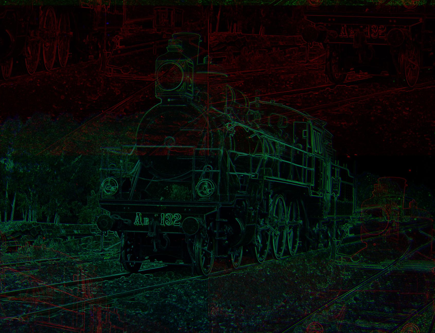
I use the method purposed in Color Transfer between Images to correct the hue of reconstructed images, since the filters used by Prokudin-Gorskii are not exactly the standard RGB.
The key is to find an orthogonal color space. The space transfer can be summarized as RGB -> LMS -> logLMS -> lαβ -> logLMS -> LMS -> RGB.
Hue correction is conducted in lab space, where the average of the chromatic channels α and β are shifted to zero. The average for the achromatic channel is unchanged, because there is no need to change the overall luminance level. The standard deviations should also remian unaltered.

Before Correction
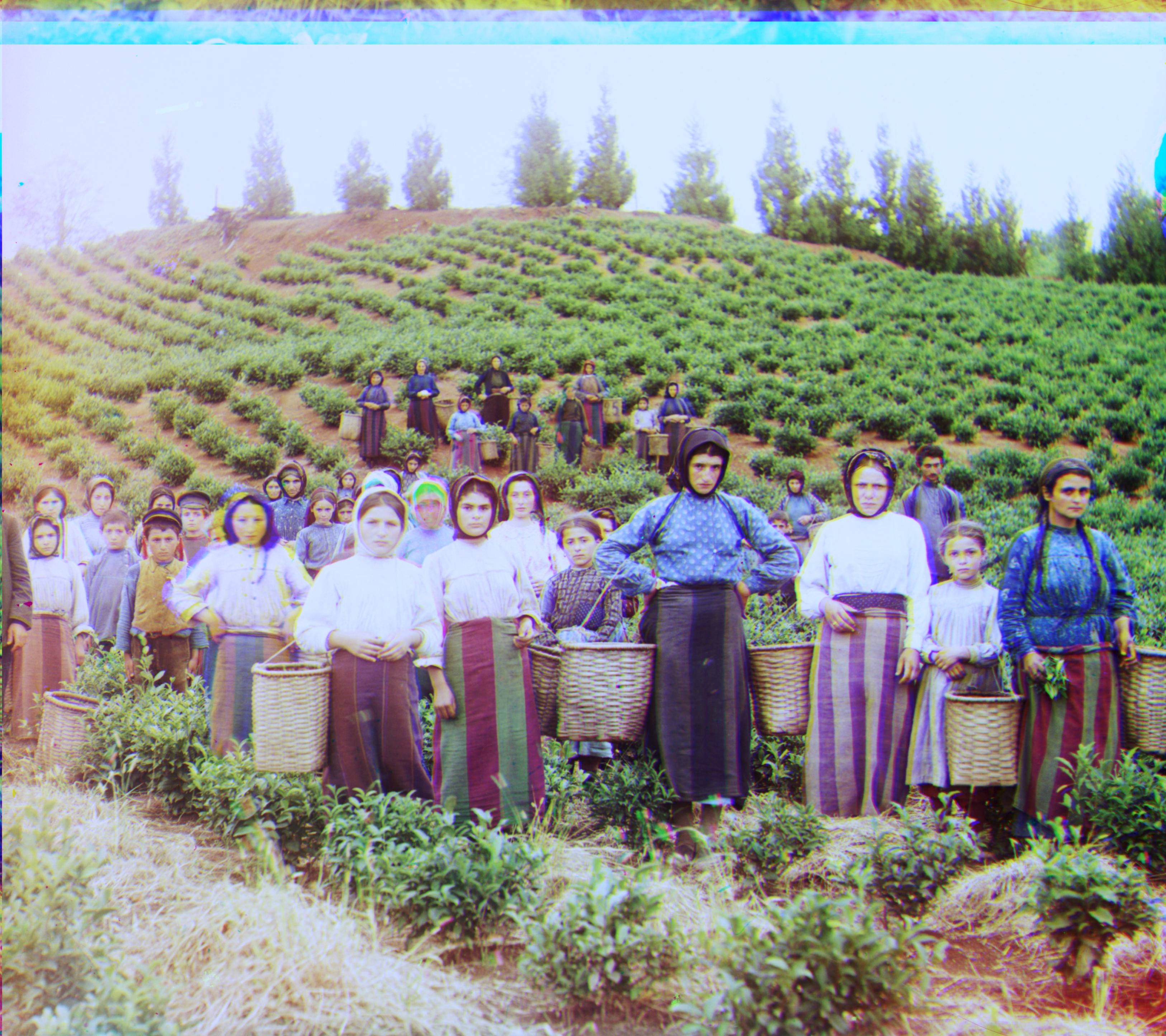
After Correction