Lab 1
The purpose of this lab is to introduce the use of the Arduino's analog input and digital I/O capabilities. You will be using a pushbutton to control the illumination of an LED and then use a potentiometer to control the state of three LEDs.
Before starting the lab please be sure that you have a working development environment. Install the IDE (Integrated Development Environment) and upload the "Blink" program.
Part List:
(3) LEDs of different colors
(3) 330 Ω
(1) 10 kΩ
(1) Pushbutton
(1) Potentiometer
Connecting wires
Part 1: Digital I/O
Breadboard Setup
For this part we will be using two digital I/O pins: one for reading the state of a pushbutton, and one for controlling an LED. Let's use digital pins 2 and 3.
First, let's connect the pushbutton to digital pin 2. The schematic for this connection is shown in Figure 2. The 5V and GND connections come from the Arduino's power connector. Note that in this configuration, when the button is not pressed, the digital input reading will be "HIGH" or 5V. When the button is pressed, the digital pin is connected directly to ground, so the reading will be "LOW" or 0 V. Could you reconfigure the circuit to flip that logic? Use a 10 kΩ resistor here (brown-black-orange). Figure 2 shows a photo of this portion of the circuit.

Figure 1: Pushbutton setup. The pushbutton is configured to read 5 V if the button is NOT pressed.
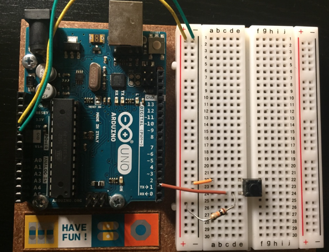
Figure 2: Pushbutton Circuit.
Now let's handle the connection to the LED. Connect the LED color of your choice to the breadboard following the schematic shown in Figure 3. Note that the "D" in LED stands for diode. We'll talk a lot more about diodes later, but for now it means that it matters which leg of the LED is connected to ground. To get it to work, connect the shorter leg to ground (also, there is a flat surface on the LED on the negative side). Nothing horrible will happen if you flip it, but it won't light up. Let's use the 330 Ohm (orange-orange-brown) resistor. Connect the top of the resistor to digital pin 1 on the Arduino. Figure 4 shows the fully completed circuit.
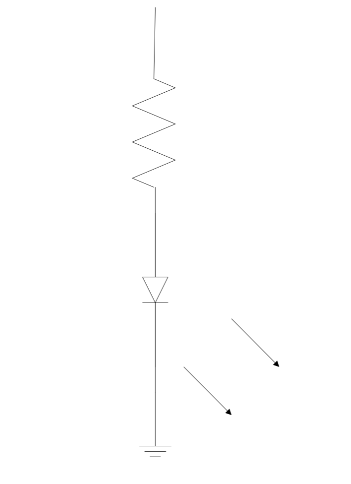
Figure 3: LED with current limiting resistor.

Figure 4: Completed circuit. Also, the resistor in this figure is 220Ω, but you will be using a 330 Ω resistor.
Code:
Let's start with the Lab 1 Part 1 code that is provided to you on Canvas. Download the code onto the Arduino, push the button, and verify that the LED turns on / off depending on the button state. This code is relatively simple, so it's important to understand all of its components.
Now that that's working, let's have you make a quick modification, show to the TA, and finish this portion. Modify your code so that the LED blinks at 1 Hz while the button IS NOT pressed, and blinks at 2 Hz while the button IS pressed.
Part 2: Analog Input
Breadboard Setup
For this portion of the lab we will be using one analog input pin to read the state of a potentiometer and three indicator LEDs to report the state.
First, let's connect potentiometer to power, ground, and analog pin A0. The 5V and GND connections come from the Arduino's power connector. The potentiometer will function as a voltage divider:

We will derive this soon!!! with the rotation of the pot changing the value of R2 but not changing the sum (10 kΩ). The output voltage will therefore change between roughly 0 and 5 V as the potentiometer sweeps through its range.Figure 5 shows a photo of this portion of the circuit.
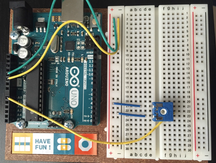
Figure 5: Potentiometer circuit. Your potentiometer looks a little bit different (still blue, but has an arrow on the knob).
Now let's connect the three LEDs to digital pins D2, D3, and D4 using the same circuit as last time (digital pin -> 330 Ω resistor -> LED -> ground). The completed circuit should look like Figure 6.
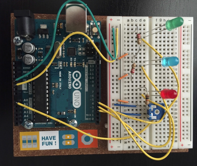
Figure 6: All the resistors in your circuit should be 330 Ω, i.e. orange-orange-brown.
Code
Now load the Lab 1 Part 2 code. This code will read from the analog input and then report the result on the serial port. The Arduino's analog inputs have 10-bit resolution, which means that voltages from 0-5 V are mapped to numbers on the range from 0 to 1023. The code to read from an analog pin is very similar to that for reading from a digital pin.
The code this week will report the value of the analog reading to the terminal in the Arduino IDE. To do this we use two functions: Serial.begin (https://www.arduino.cc/en/Serial/Begin) and Serial.print/println (https://www.arduino.cc/en/Serial/Print). Data from the Arduino is available through the Serial Monitor, which can be started under the Tools menu. Opening the Serial Monitor also restarts the program uploaded into the Arduino.
Download the code onto the Arduino, turn the potentiometers, and watch the values change on the serial monitor.
Your turn...
Now that that's working, let's have you make a quick modification.
Modify your code so that the voltage (floating point) is displayed at the serial terminal, and turn on the LEDs according to the following rule:
None lit if the voltage is between 0 and 1.25 V
One lit if the voltage is between 1.25 and 2.5 V
Two lit if the voltage is between 2.5 and 3.75 V
All lit if the voltage is between 3.75 and 5 V.
Show to the TA when finished to receive credit for this lab. Great work!