Lab 3: Op Amps & Diodes
The purpose of this lab is to demonstrate basic op amp and diode circuits. This is a circuits-only lab, i.e. you will not be using the Arduino during the lab.
Before starting the lab please be sure that you have the NScope software (which you can download here).
Part List:
(1) LM324N Op Amp
(3) 330 Ω Resistor
(1) 100 μF Capacitors
(1) Photoresistor
(1) LED
(1) Diode
(1) Push Button
Connecting wires
Part 1: Op Amps
This section will focus on two popular op amp circuits -- the inverting amplifier and the comparator. For each we will use the NScope and other components to analyze behavior.
Figure 1 shows the op amp chip we will be using for this lab. Instead of grounding pin 11, we will connect it to the NScope's -5V supply to have bipolar operation. Place the op amp chip on your breadboard and power it from the NScope's 5 and -5 V supplies, being careful to connect the polarity correctly.
Figure 2 shows the correct connections for powering the chip. Note that the chip's notch is facing away from the NScope in figure 2.

Figure 1: LM324N Pinout. The chip contains 4 separate op amps. Note the notch in the package...it's important to connect the power with the correct polarity!

Figure 2: Op Amp Power Connections. Polarity matters!
Inverting Amplifier
Now we will build an inverting op amp that multiplies the input by a factor of 2. Using the op amp circuit of your choice and 330 Ω resistors:
1] Connect two resistors in parallel from the NScope output A1 to the negative terminal of the op amp.
2] Connect one resistor between the negative terminal of the op amp and its output.
3] Ground the positive terminal of the op amp.
The circuit diagram is shown in Figure 2 and the completed circuit is shown in Figure 4.
Now open the NScope software, send a sine wave of amplitude 1 into the circuit, and view the signal from A1 and the op amp output on the NScope. You should see something like the output shown in Figure 2. Now play with the amplitude of the waveform and note what happens as the amplitude gets big. What's the largest amplitude that successfully passes through unclipped?
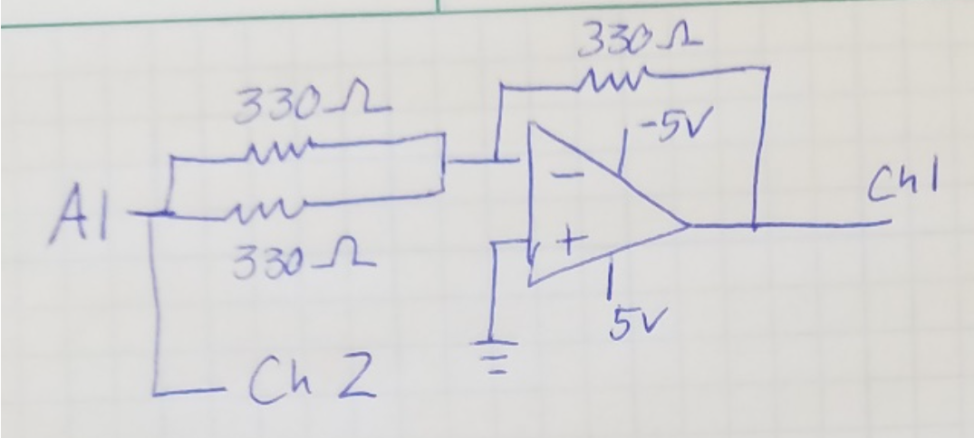
Figure 3: Inverting Op Amp Circuit Diagram
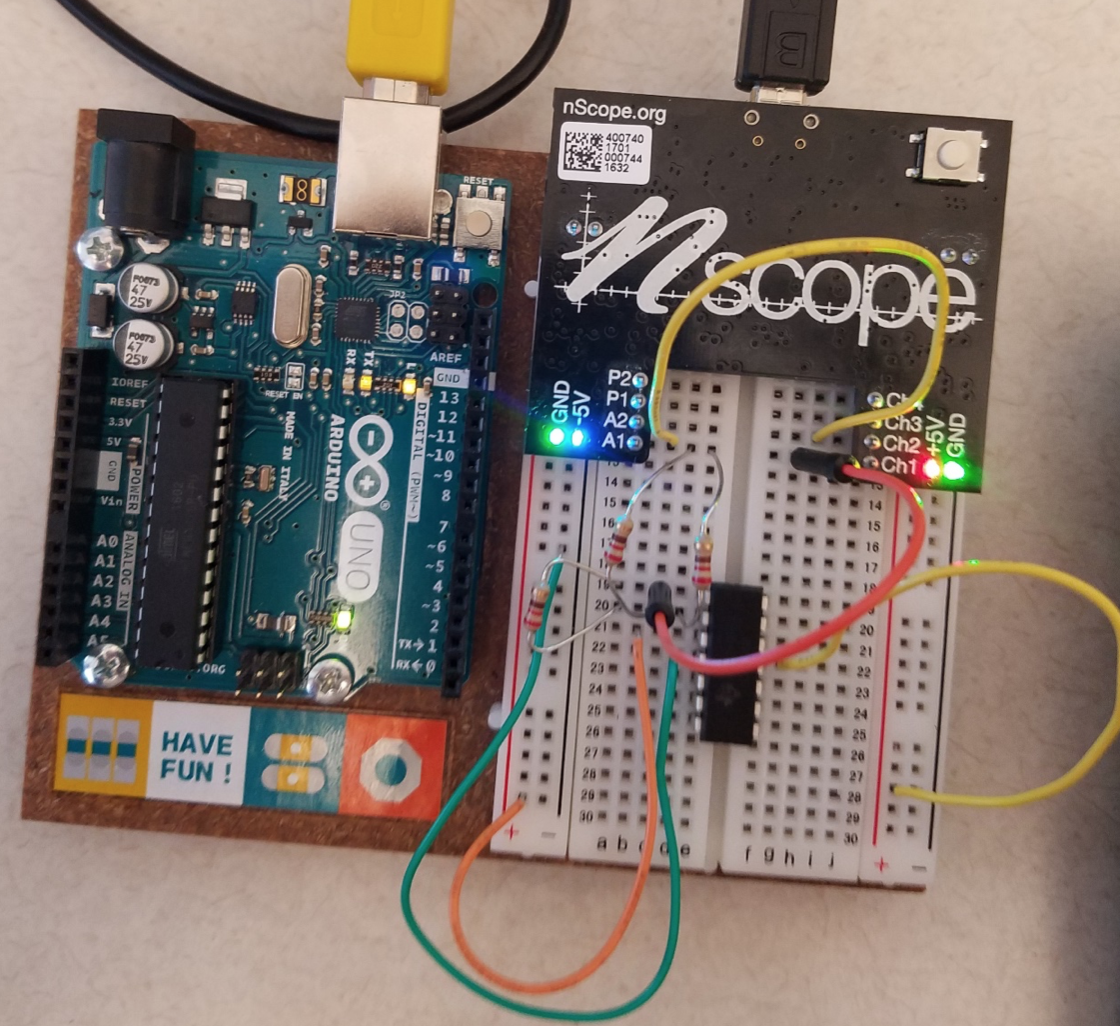
Figure 4: Inverting Op Amp Circuit. The parallel resistors from A1 to the negative terminal are used to get a gain of 2.

Figure 5: Inverting Amplifier Performance. The output signal (red) is -2x the input signal.
Your Turn
1] Pass the output of the op amp through a 2nd inverting amplifier stage with a gain of 1. The op amp of this 2nd op amp should now be twice the input signal, with no sign change.
2] Build a non-inverting op amp with a gain of 2. Here you should only need to use two resistors.
Comparator
Now we'll remove the feedback and use the op amp as a comparator. For this portion we'll build a circuit that turns on an LED when a light sensor is covered (this has obvious practical applications, e.g. automatic night lights). To build this circuit we need to build a couple of voltage dividers: one to create a 2.5 V source based on the 5V NScope source, and one to interface the resistive sensor. The full connections are as follows:
1] Modify the op amp power so that the negative terminal is connected to ground instead of -5V.
2] Connect two 330 Ω resistors in series from 5V to ground. Connect the point where the resistors meet to the positive terminal of the op amp of your choice.
3] Connect the photoresistor and a 10 kΩ resistor in series from 5V to ground, with the photoresistor connected to 5V. Connect the point where the two meet to the negative terminal of the op amp.
4] Connect an LED in series with a 330 Ω resistor from the op amp output to ground. This LED should now turn on when you block the light to the photoresistor. You can also connect the op amp output to the NScope to see the changes as the resistor is covered.
The circuit diagram is shown in Figure 6 and the completed circuit is shown in Figure 7. Comparators can be used to build control circuits like this, but can also be used to convert analog outputs into digital outputs if we care only when a signal crosses a threshold.

Figure 6: Comparator Circuit Diagram
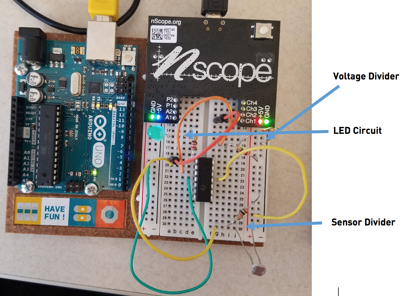
Figure 7: Comparator Circuit
Your Turn
1] Use a potentiometer to make an adjustable voltage divider. Use this to change the sensitivity of the circuit, i.e. make the light turn on when the detector is only slightly blocked.
2] Change the circuit so the light turns on when the photoresistor sees light instead of darkness.
Part 2: Diodes
Now let's look at a couple of simple diode circuits - the 1/2 wave rectifier, and the peak detector.
1/2 Wave Rectifier
Let's build the simplest diode circuit and test its performance.
1] Connect the resistor and diode in series from the analog pin A1 to ground, with the resistor connected to pin A1.
2] Connect the analog source to one of the scope channels and the connection point between the resistor and diode to the other connection point.
3] Put a bipolar sine wave into the circuit with amplitude 4.75 V.
You should see something like Figure 3, with the clipping on the bottom possibly depending on your diode configuration.
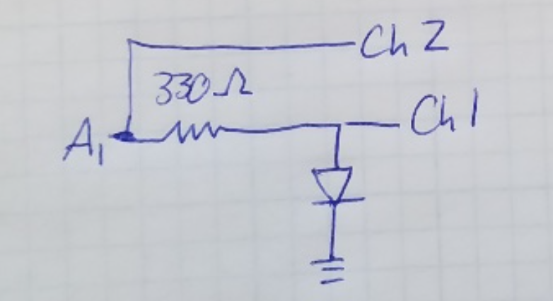
Figure 8: 1/2 Wave Rectifier Circuit Diagram
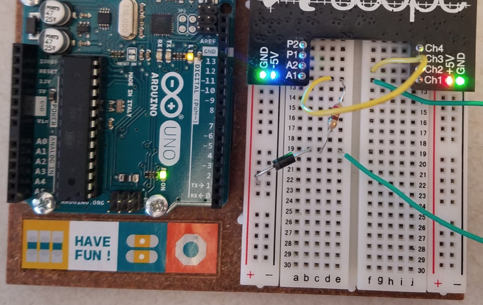
Figure 9: 1/2 Wave Rectifier Circuit

Figure 10: 1/2 Wave Rectifier Performance
Your Turn
1] Flip the polarity (direction) of the diode.
2] Switch the order of the resistor and diode.
2] Notice the change and show the TA!
Peak Detector
1] Connect the diode in series with a capacitor to ground. The diode should point towards the capacitor.
2] Connect a switch in parallel with the capacitor. This will allow us to reset the peak detector when the button is pressed.
3] Read the capacitor voltage and the signal A1 on the NScope.
Now send a waveform through the peak detector and note the output behavior. Turn the analog output off to show the holding operation of the capacitor.
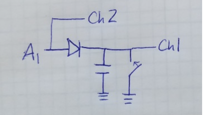
Figure 11: Peak Detect Circuit Diagram.
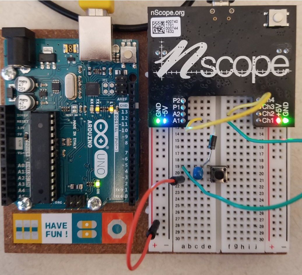
Figure 12: Peak detect circuit. The button is used to reset the peak detector. You shouldn't hold the button down...it's shorting A1 to ground when held. Just tap to reset.
Your Turn
1] Flip the polarity of the diode and observe the behavior.
2] Show the TA!
Part 3: Sample and Hold
For the last portion of the lab, you will build a sample and hold circuit.
Your Turn
You can find the circuit diagram for a sample and hold circuit in your notes. Demonstrate the circuit performance -when you push the button, the output should give the current value of the input from A1. Now place a low frequency sine or triangle wave into the circuit and show that it you jam the button you can make the output closely match the input. You should see something like Figure 13 if you tap the button quickly.
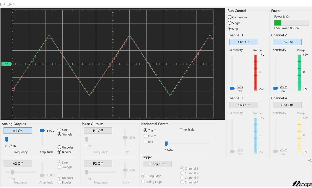
Figure 13: Sample and Hold Performance
Show to the TA and you're good to go!