4A. Apply Boundary Conditions


As stated in the problem description, the quarter plate is constrained from displacing in the x direction on the left side, and is constrained from displacing in the y direction on the bottom side. To model symmetry conditions along these two edges, in this step we will apply loads to the plate.

PREPROCESSOR -> Loads

      LOADS -> Define Loads

DEFINE LOADS -> Apply

           APPLY -> Structural

                 STRUCTURAL -> Displacement

                          DISPLACEMENTS -> On Lines


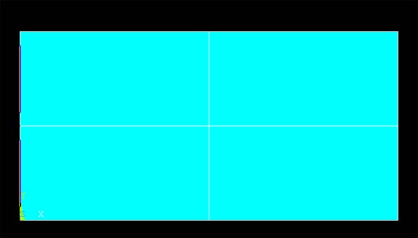
ANSYS GRAPHICS WINDOW -> Select the line on the left edge of the quarter plate (At x=0). Click APPLY in the U, ROT ON LINES window.


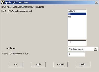
APPLY U, ROT ON LINES -> Select UX. Then enter zero for displacement value and APPLY (See figure below). This constrains the points on the left side of the plate from moving in the X direction.


PREPROCESSOR -> Loads

      LOADS -> Define Loads

DEFINE LOADS -> Apply

           APPLY -> Structural

                 DISPLACEMENTS -> On nodes

ANSYS GRAPHICS WINDOW -> Select the line on the bottom edge of the quarter plate (At y=0). Click APPLY in the U, ROT ON LINES window.

APPLY U, ROT ON LINES -> Select UY and enter zero for displacement value and APPLY. This constrains the points on the bottom of the plate from moving in the Y-direction.


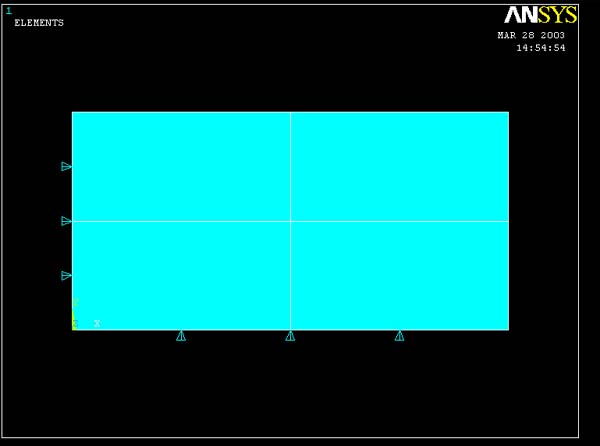
The ANSYS GRAPHICS window should now display the plate as shown in the figure below. The arrows marks the lines which are limited to zero displacement.


GO TO STEP 4B