Project 1
Colorizing the Prokudin-Gorskii Photo Collection
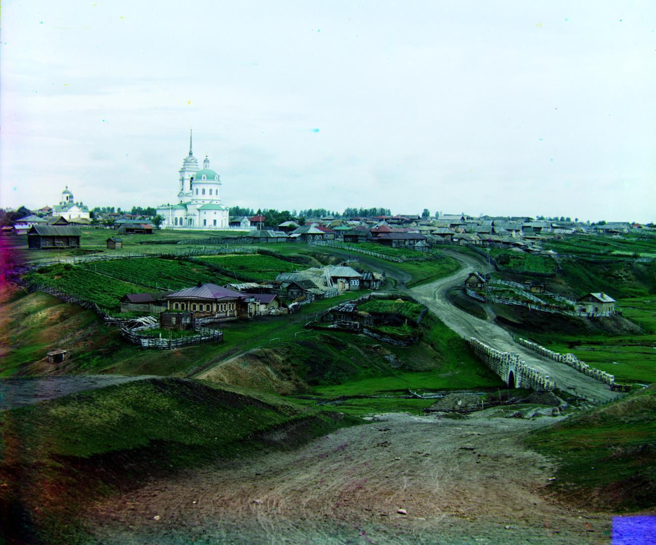
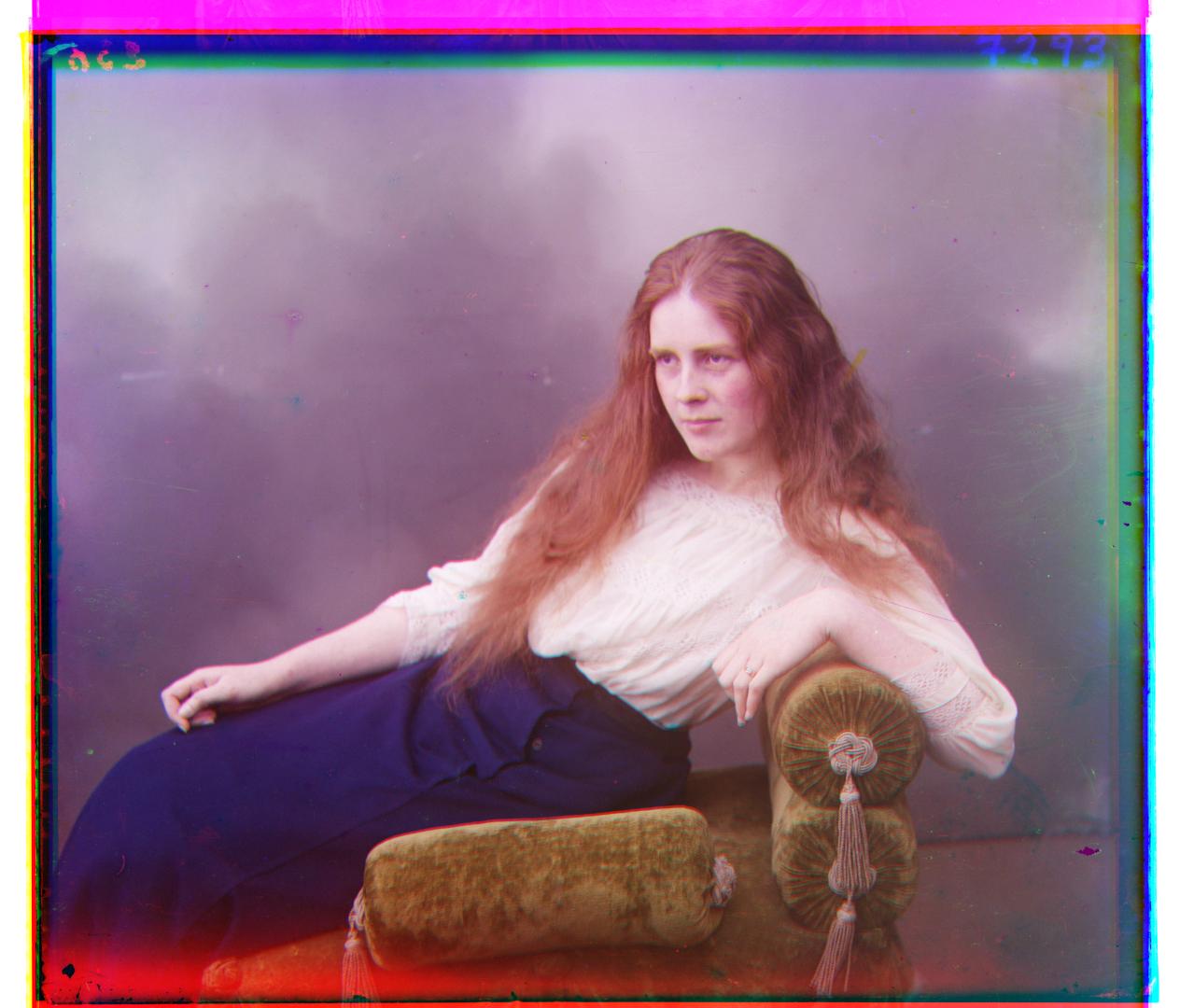
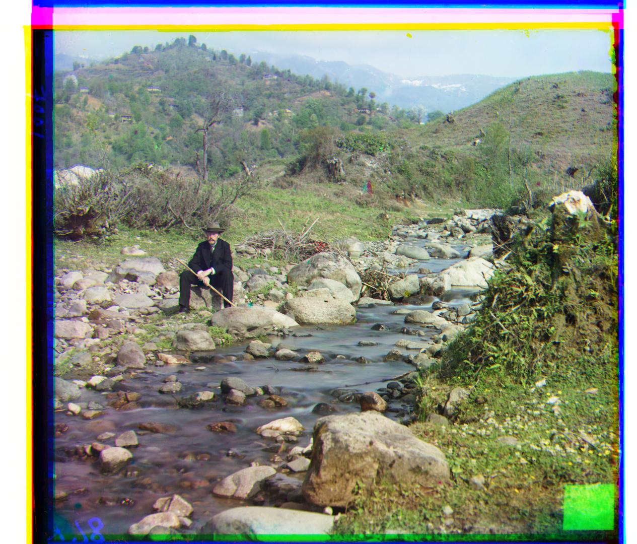
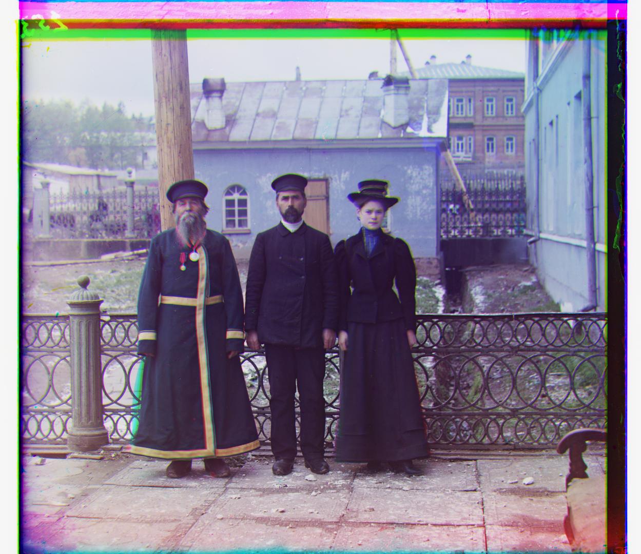
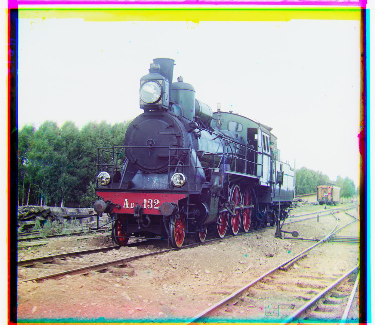
This project is an attempt to formulate and test an approach to aligning the blue, red and green channels of the Prokudin-Gorskii photo collection.
- For smaller images, an exhaustive search was conducted on various translation offsets for each channel. Each pair of translation offsets we analyzed for similarity using an L2 error on an inner subset of pixels.
- For larger images, a Laplacian pyramid was computed and image alignment was performed at each step.
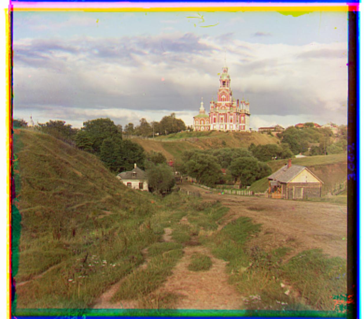
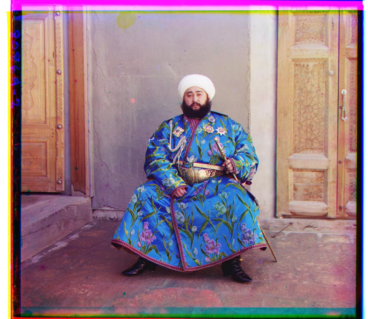
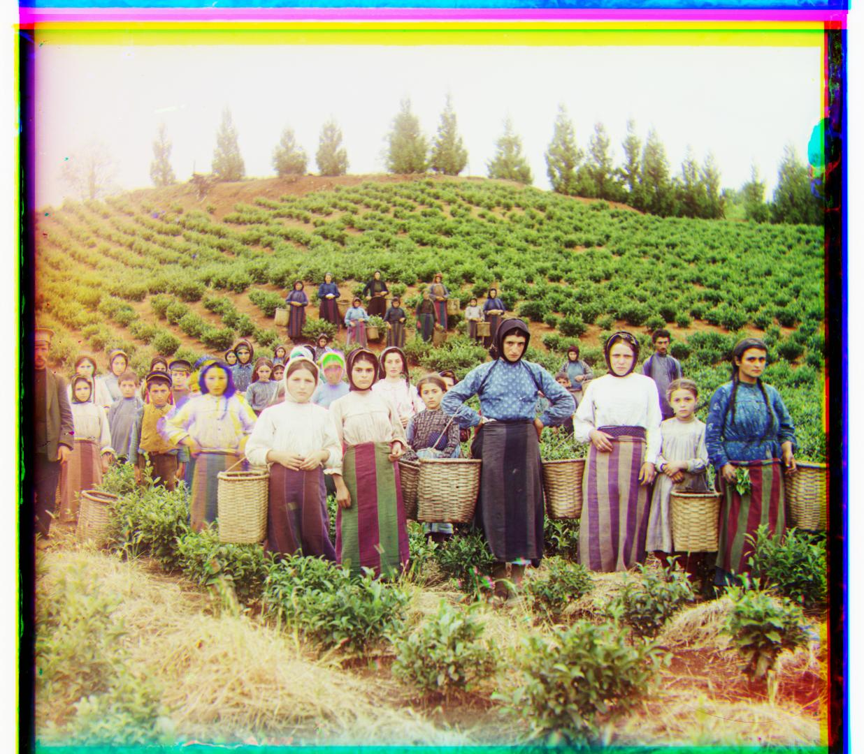
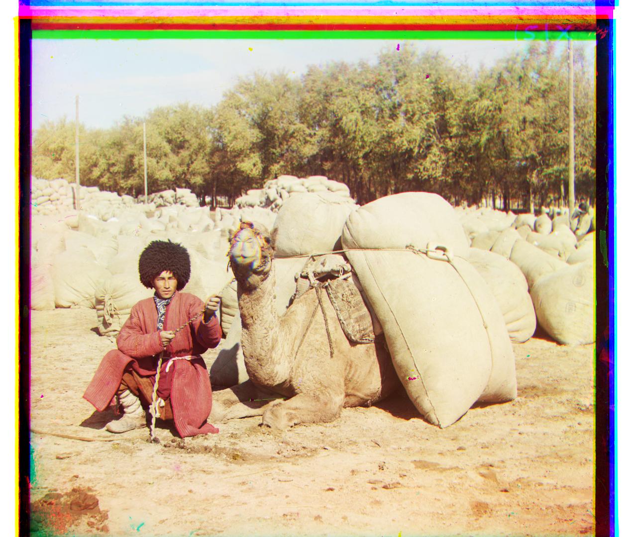
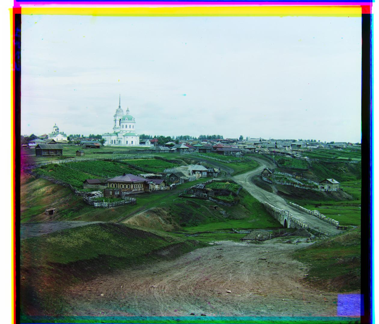
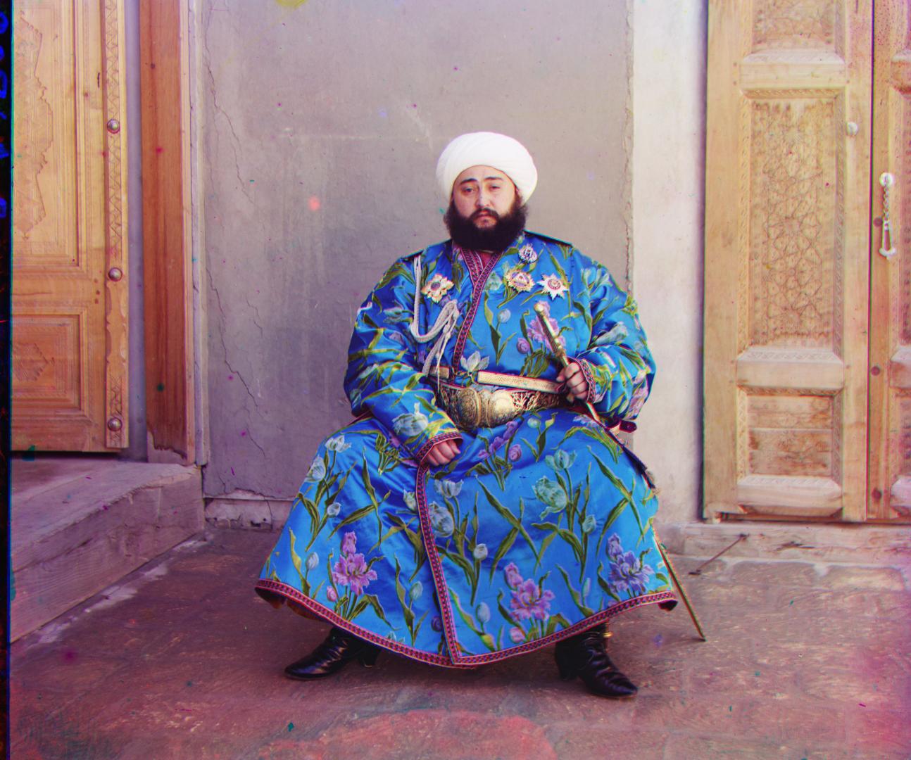
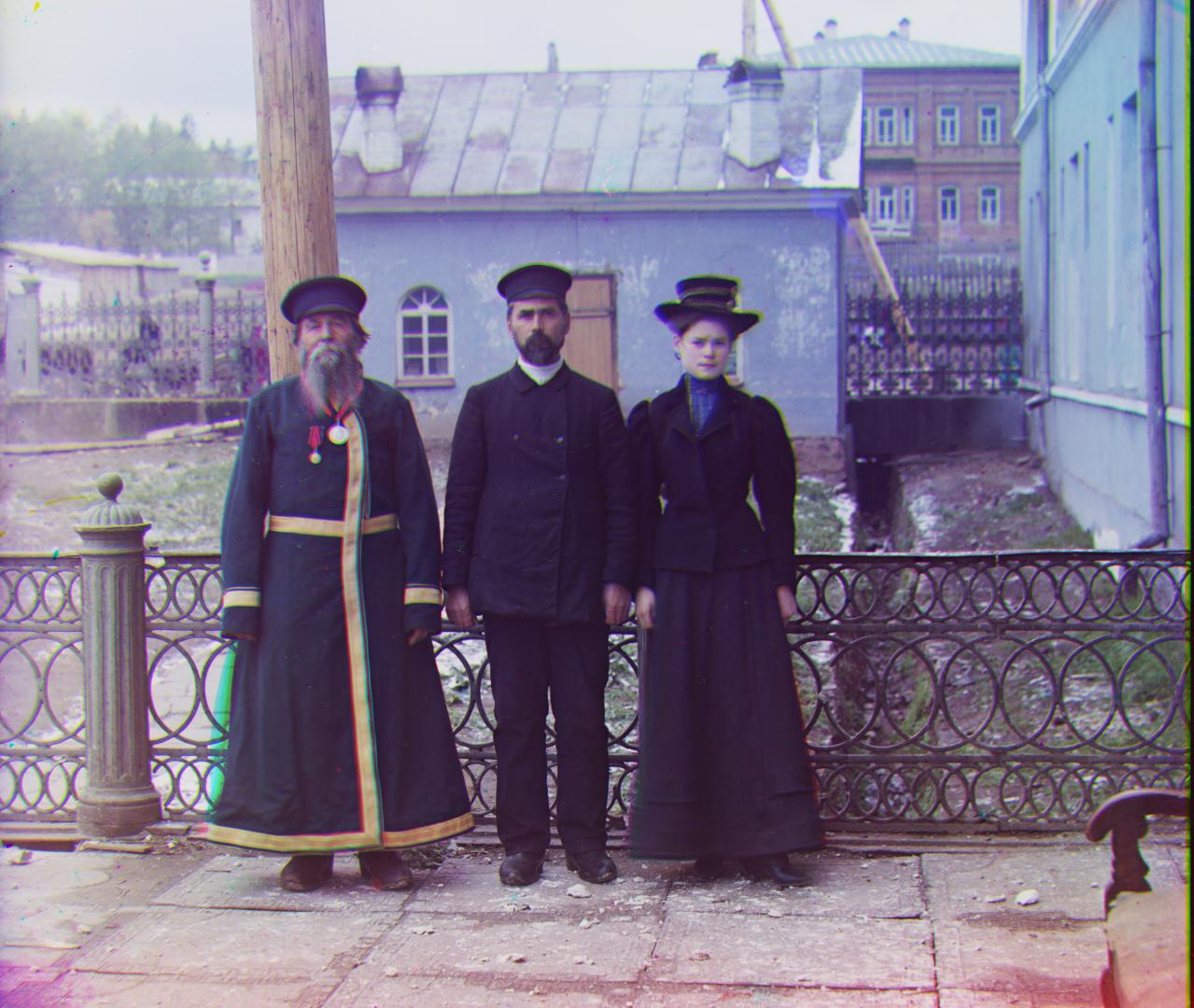
The resultant images are rescaled for size and shown below, together with the calculated offset for alignment for each channel.
Channel Alignment for Example Images
Each image has been resized to a height of 1080px while maintaining aspect ratio.
The offsets (row, col) for each channel (G, R) with respect to B can be found from hovering over the image.
Challenges
- While looping over all possible translations was relatively straightforward, tuning the scale factor for the Laplacian pyramids was a challenge.
- If the factor was too small, the offsets calculated would vary too much, and could sometimes be translated too far off.
- If the factor was too large, the runtime would suffer as a larger search space would have to be used with images of a higher resolution.
- Initially, I also did not take into account the edge effects, leading to poor alignment. This issue was solved after removing a fraction of each channel's edge.
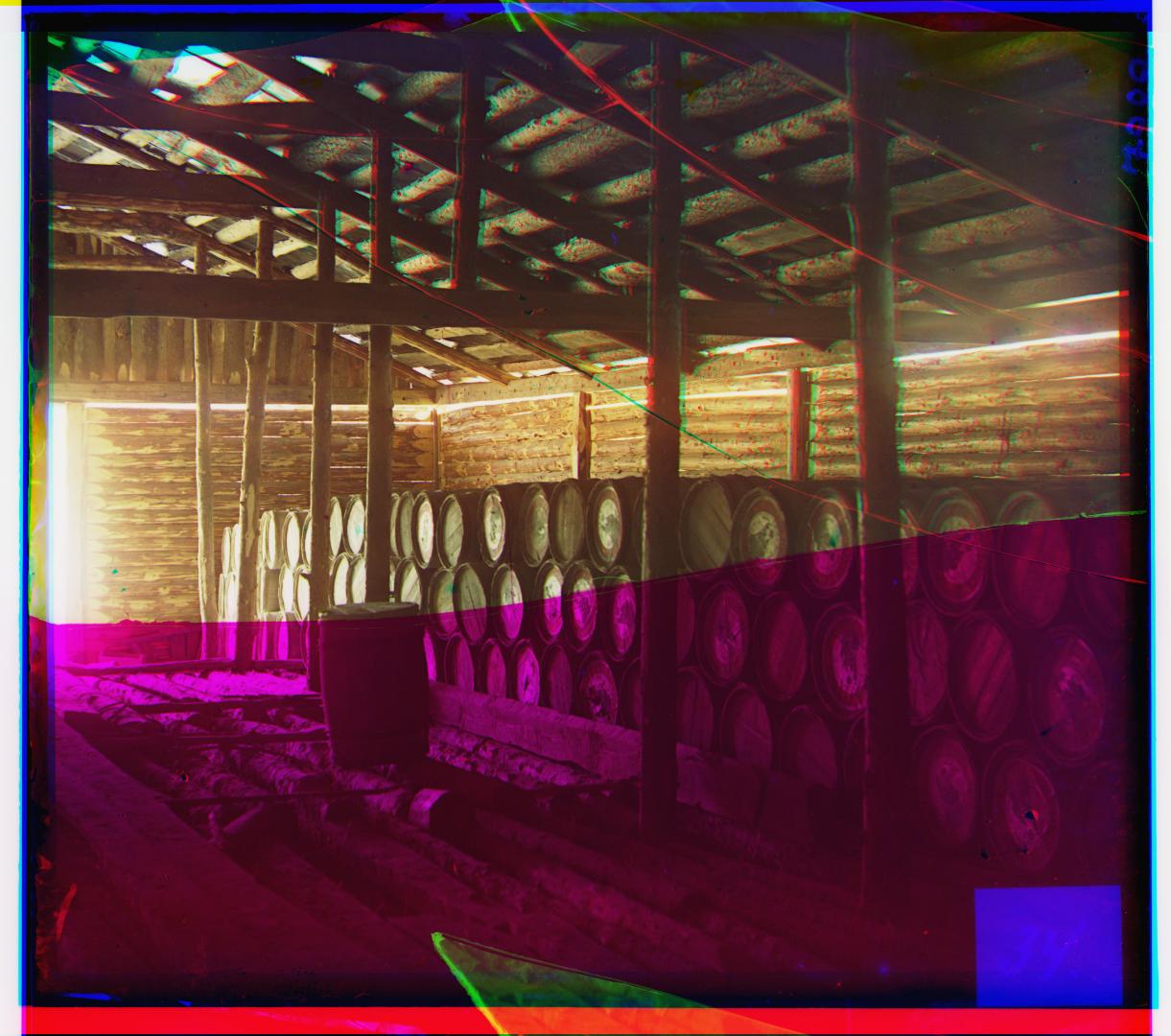
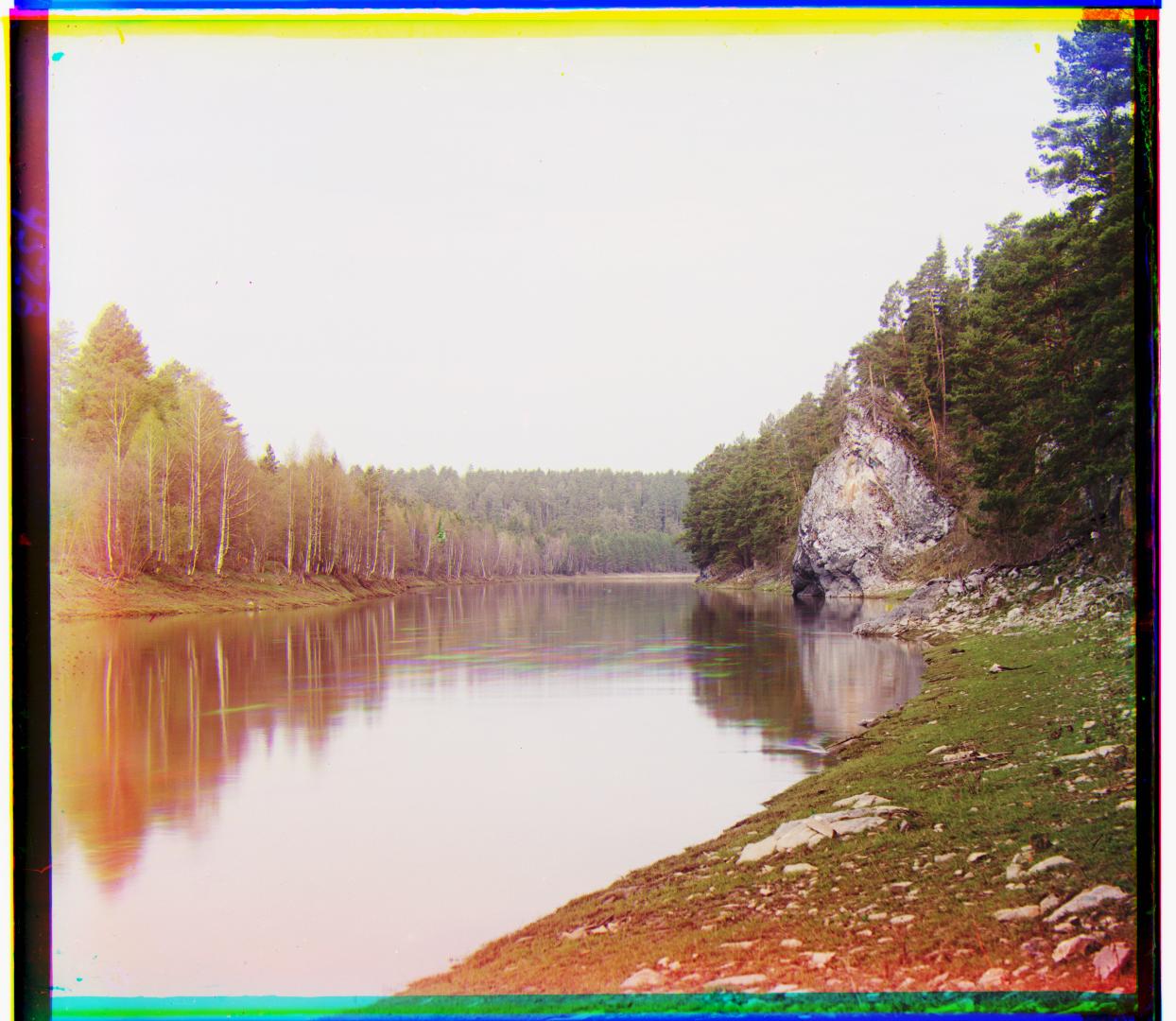
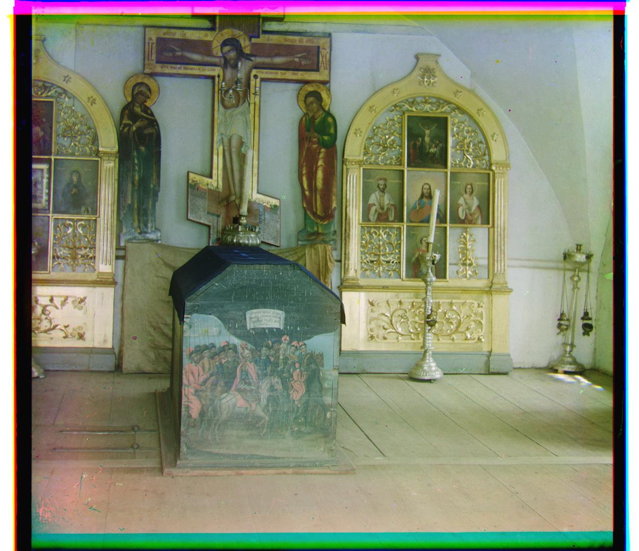
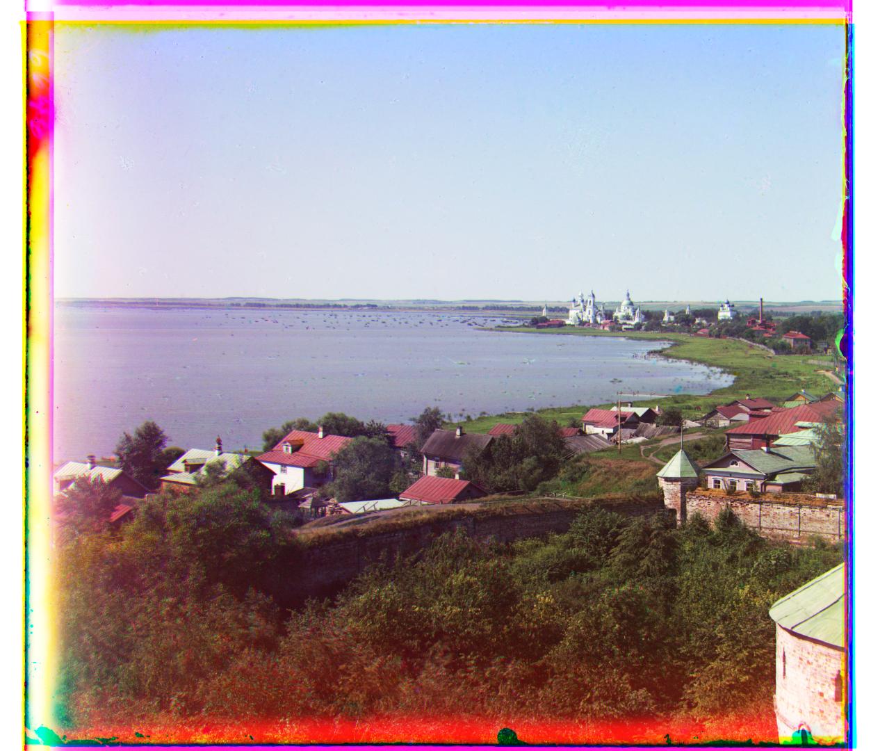
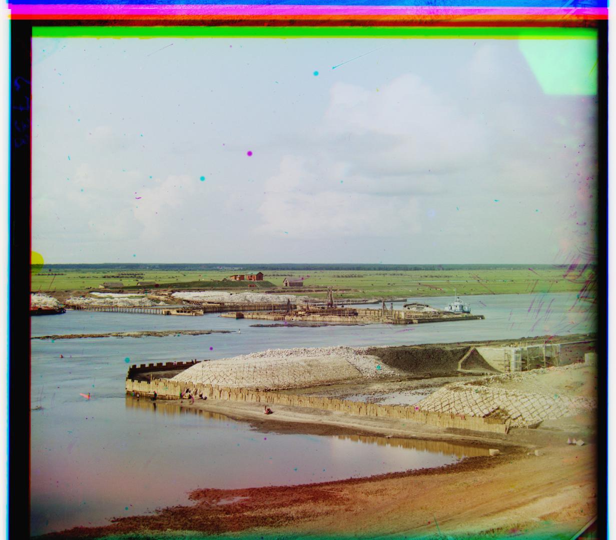
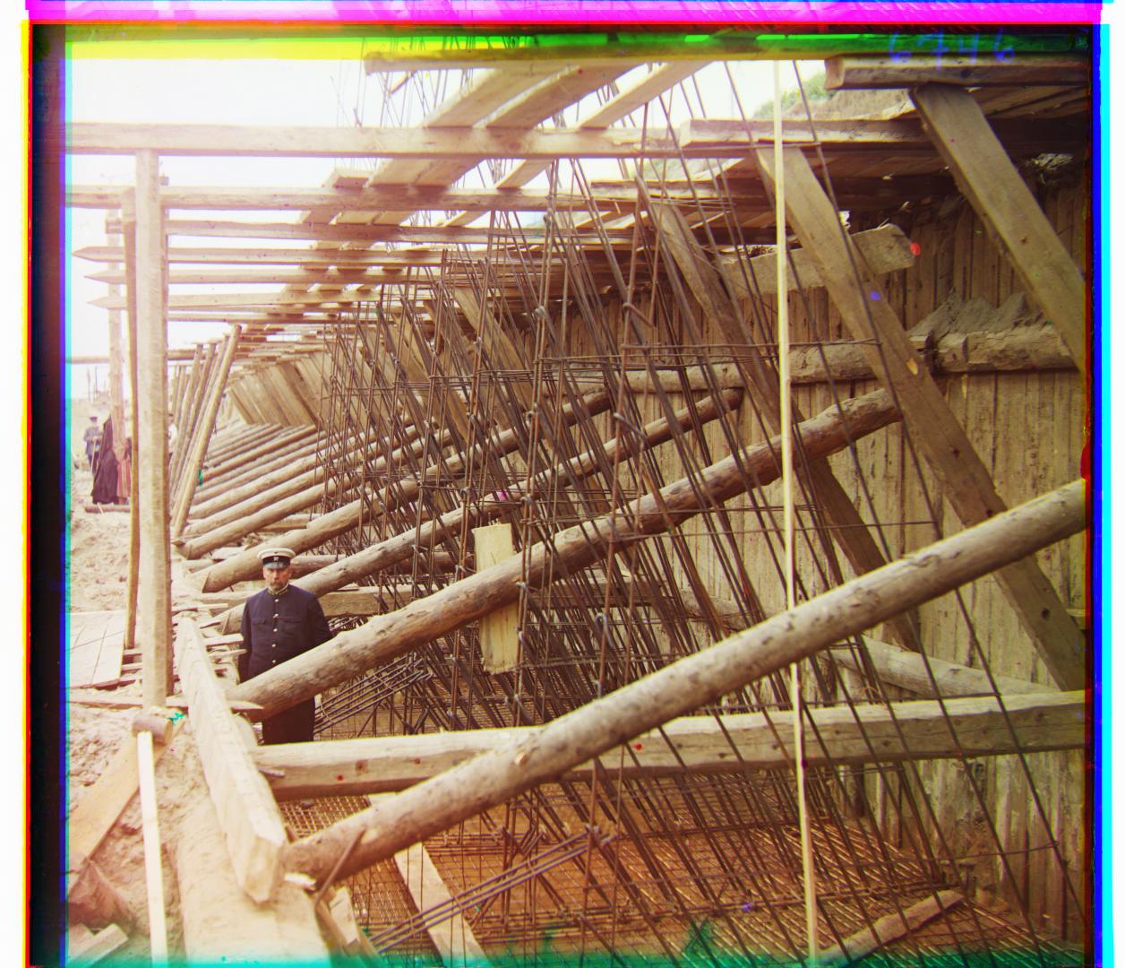
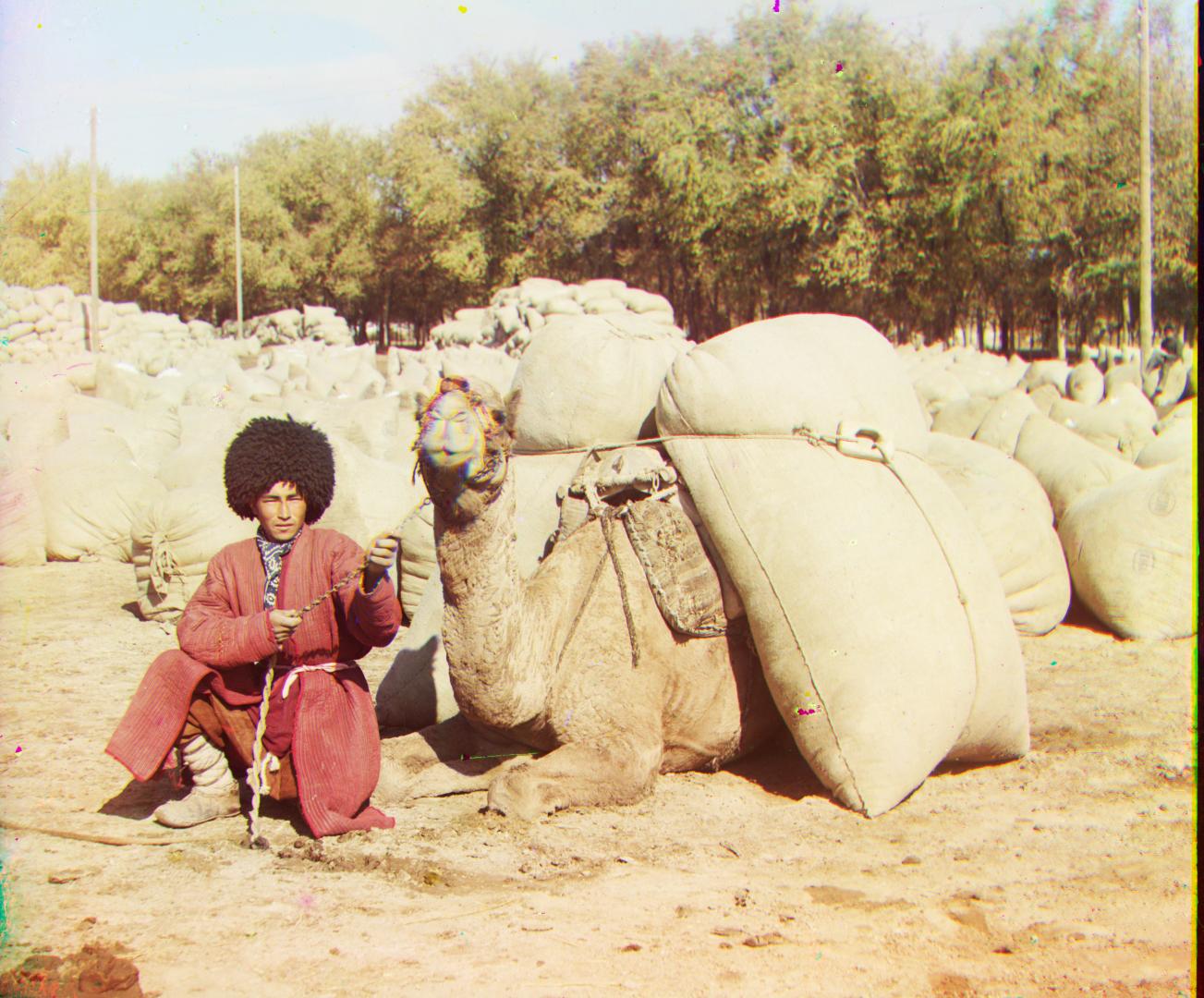
Channel Alignment for Extra Images from the Photo Collection
Bells and Whistles
Using Gradient Features for Alignment
Instead of computing the loss over normalized pixel values, it might be advantageous to extract edge features from each channel and match those instead.
Using an xy-Sobel filter, edge features from each channel are extracted.
Then, a similar procedure as above is used for channel matching.
In comparing both sets of images, it is relatively difficult to see any differences since the original alignment works relatively well.
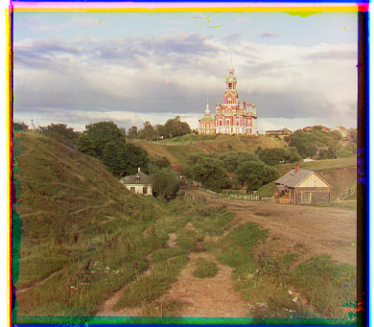
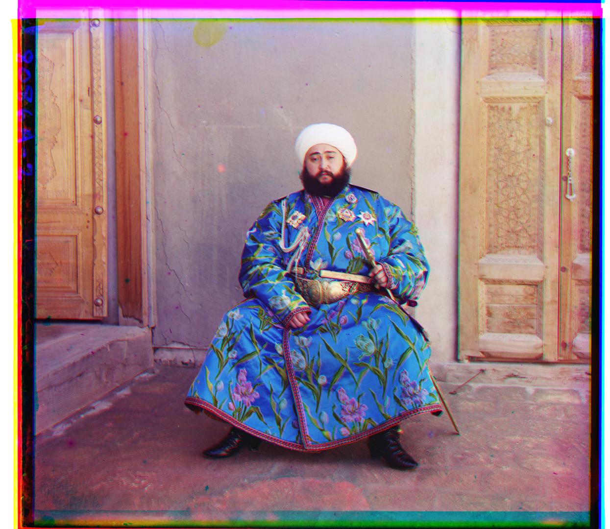
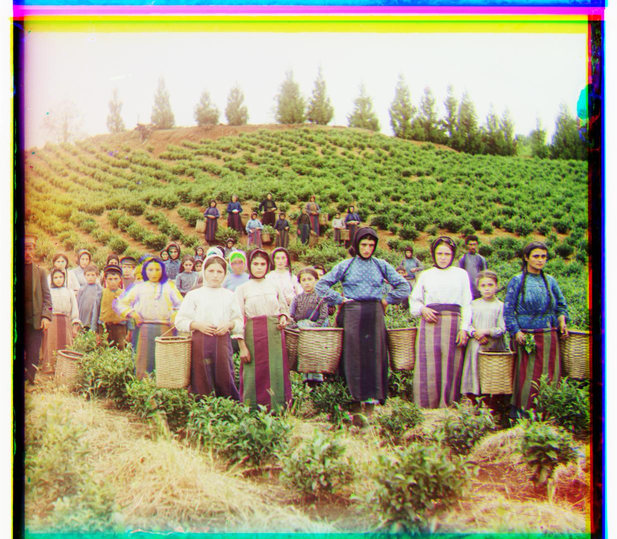
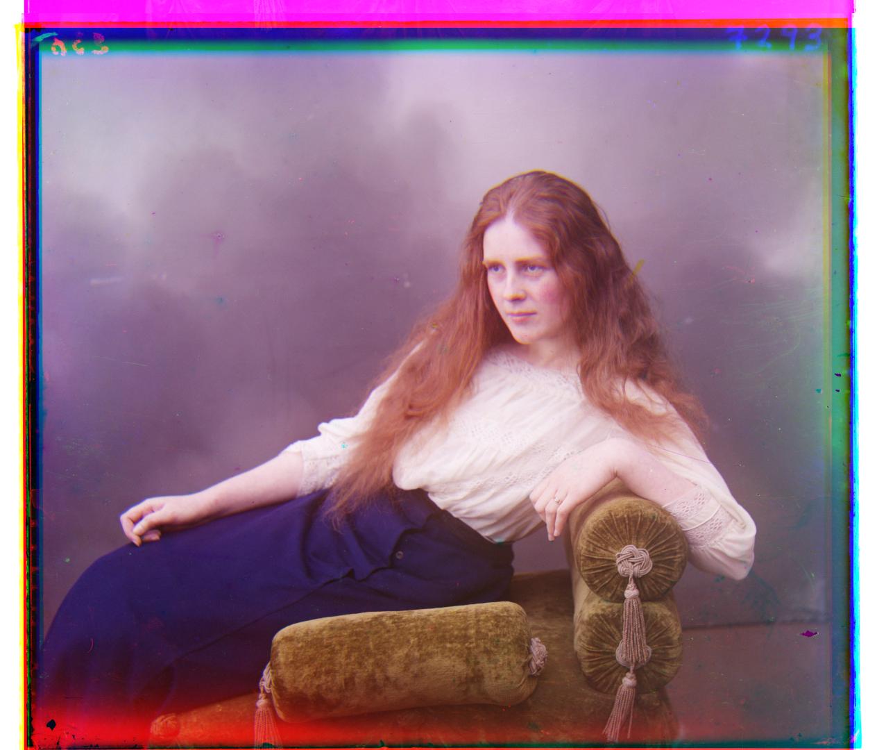
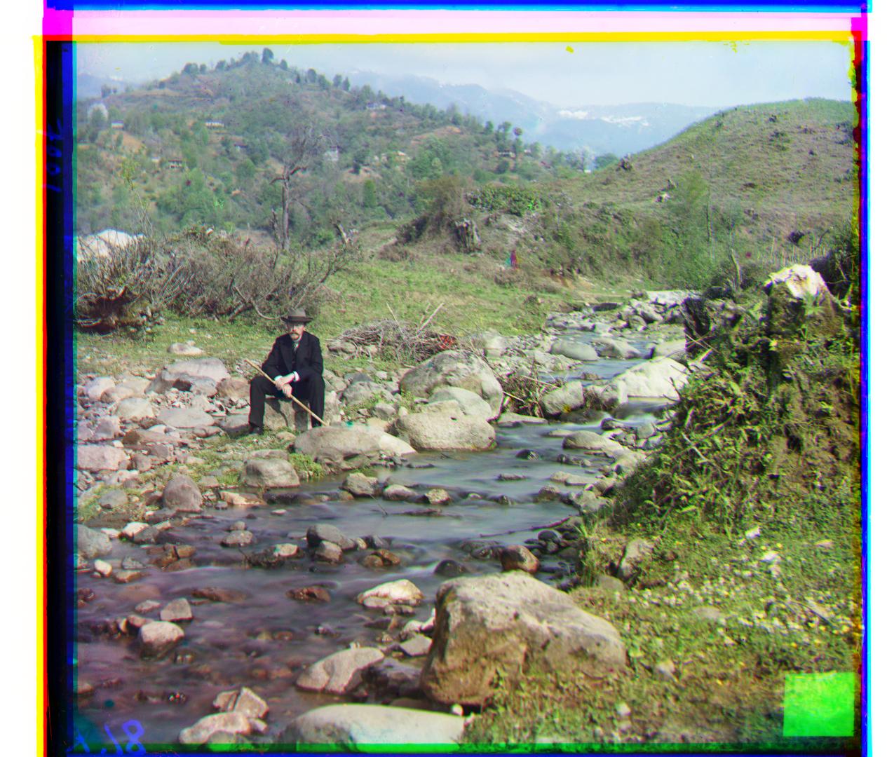
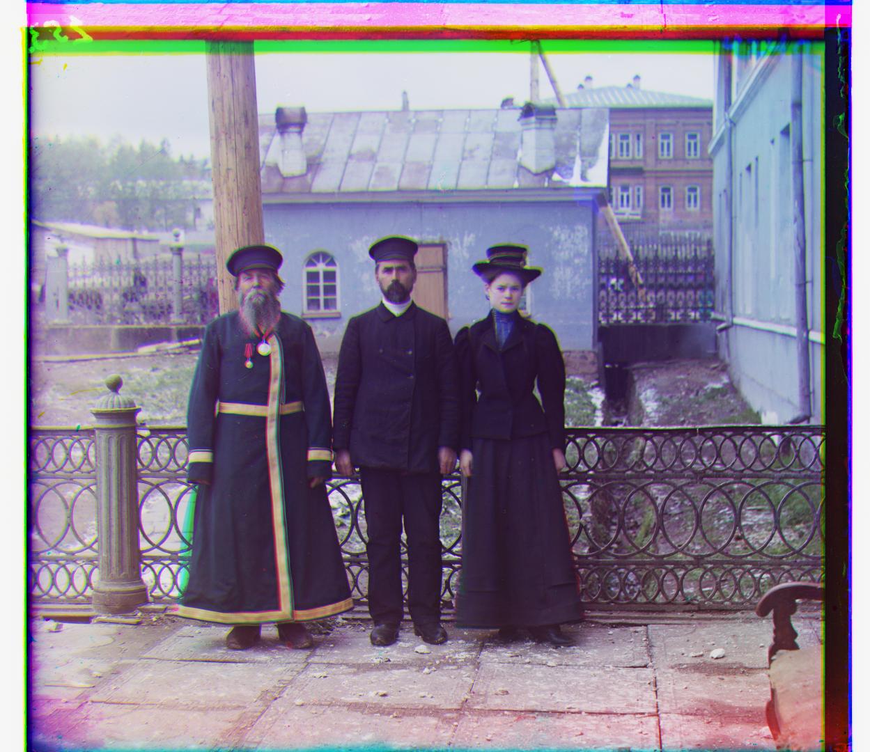
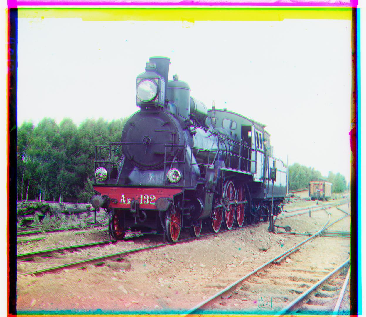
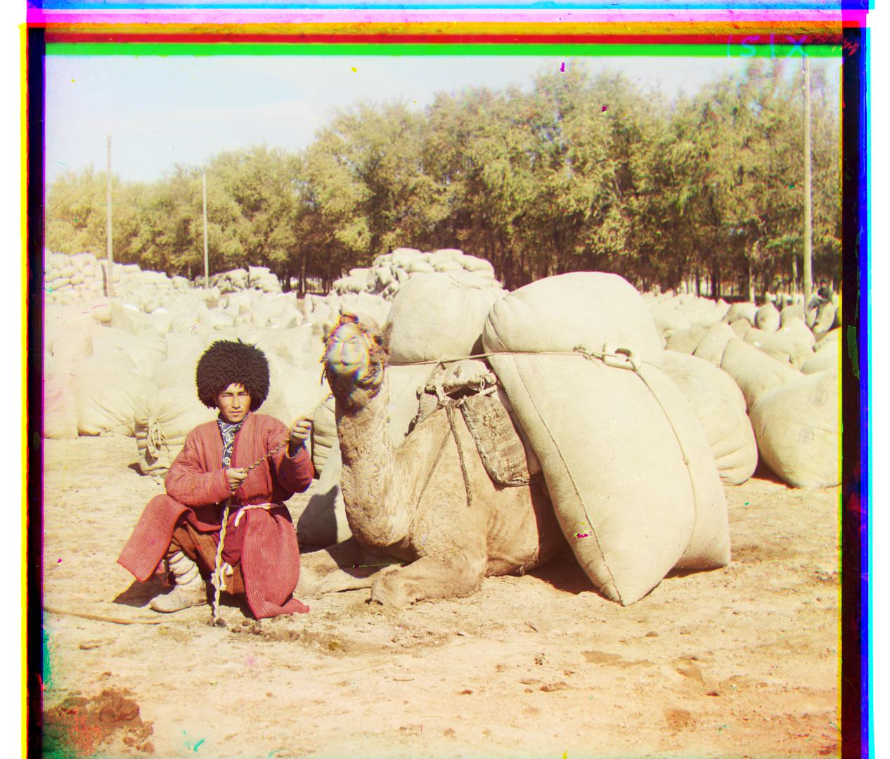
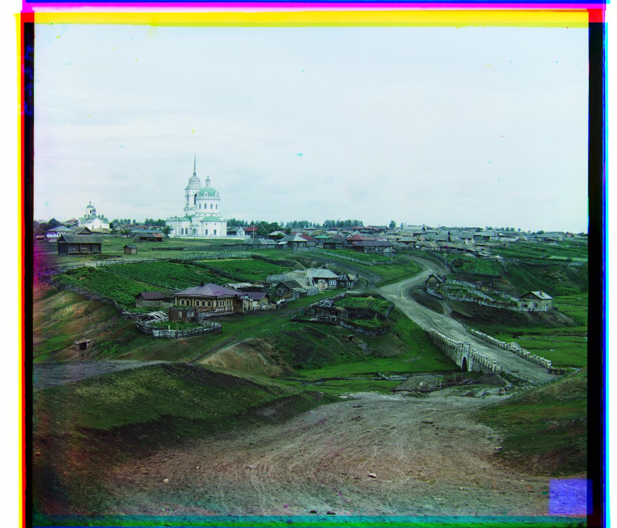
Edge Detection
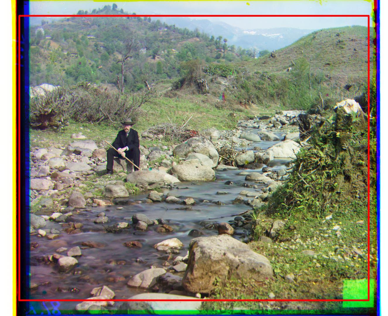
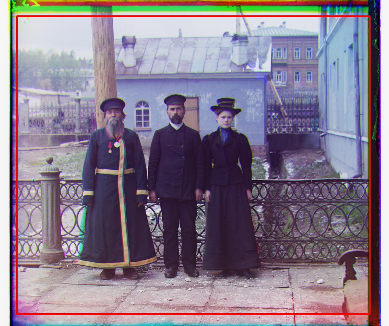
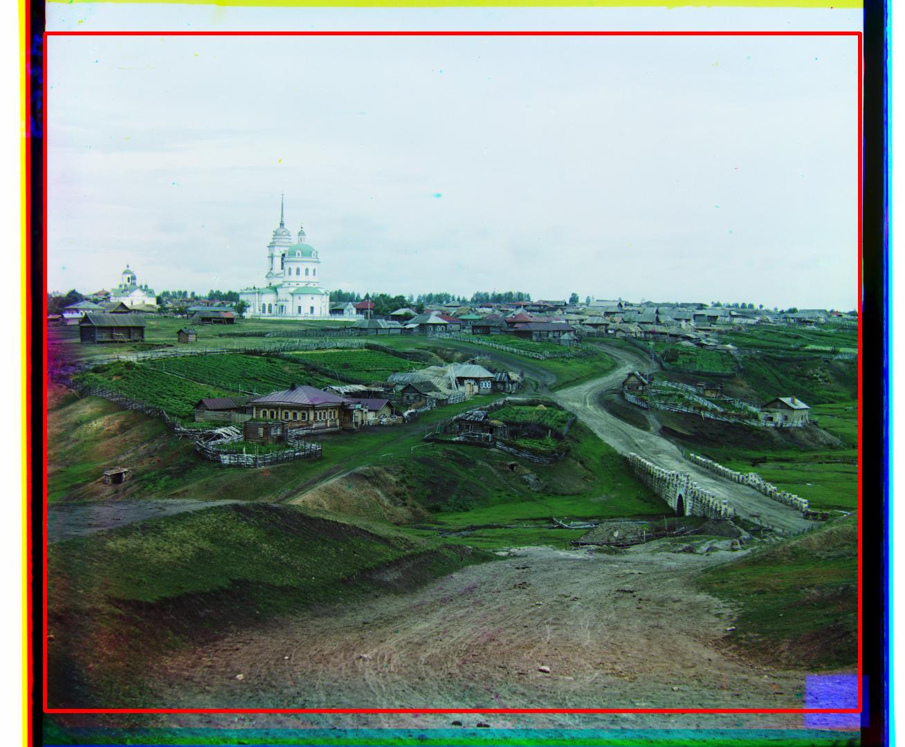
Edge detection was formulated as a two-step process.
Firstly, given that the green and red channels were rolled, any portion of the image that was rolled over was removed.
Secondly, a horizontal and vertical Sobel filter was run across the three channels of the image.
Then, depending on the orientation of the filter, a mean value for the pixels of each column / row was computed.
Since higher values correspond to a higher chance of a straight edge, given a threshold value, the last spike value was calculated for each of the four edges and three channels.
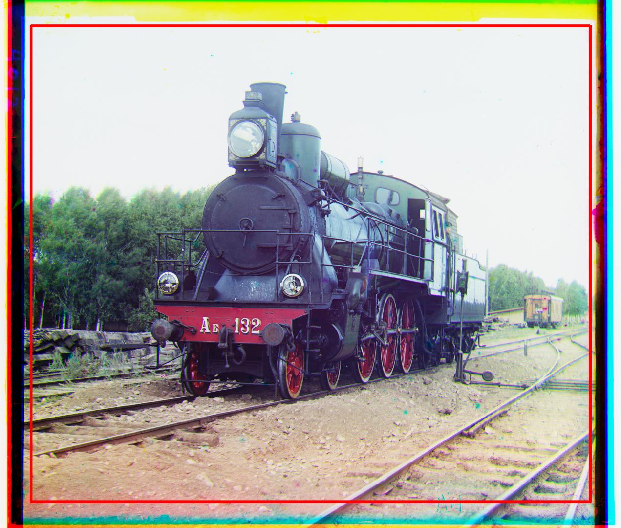
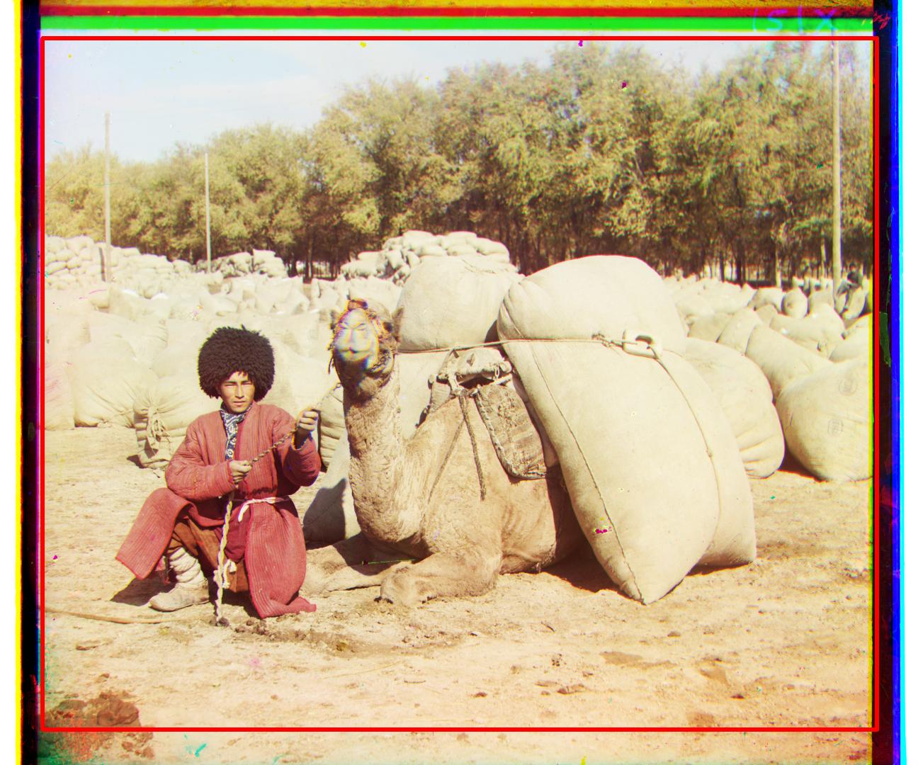
All pixels that were to the side of these extreme spikes were then removed.
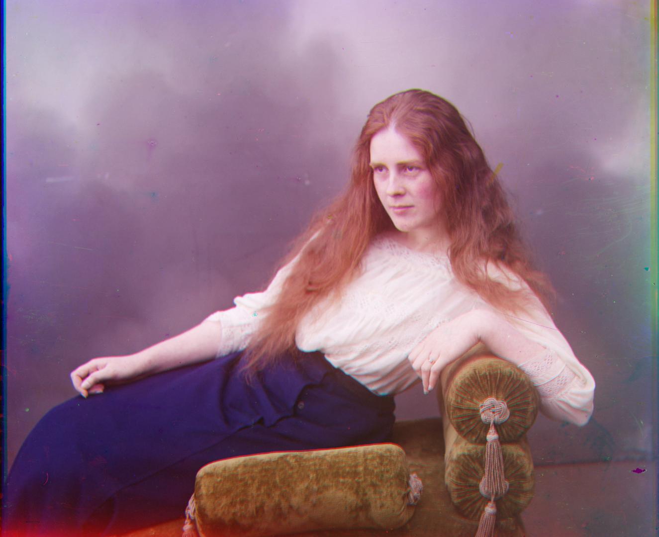
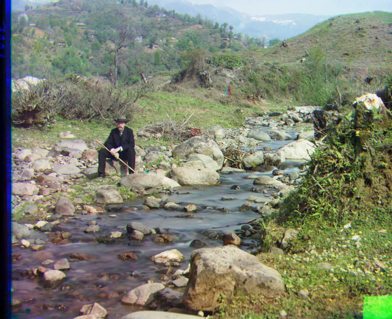
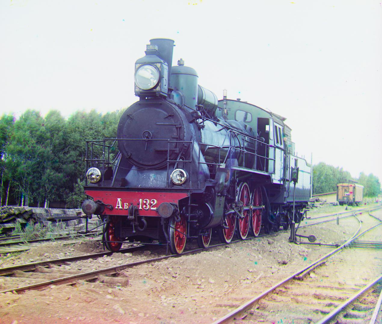
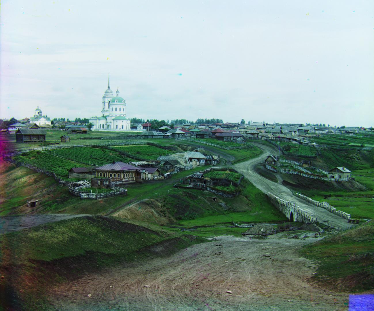
The results on several examples are shown below.
Cropped Region
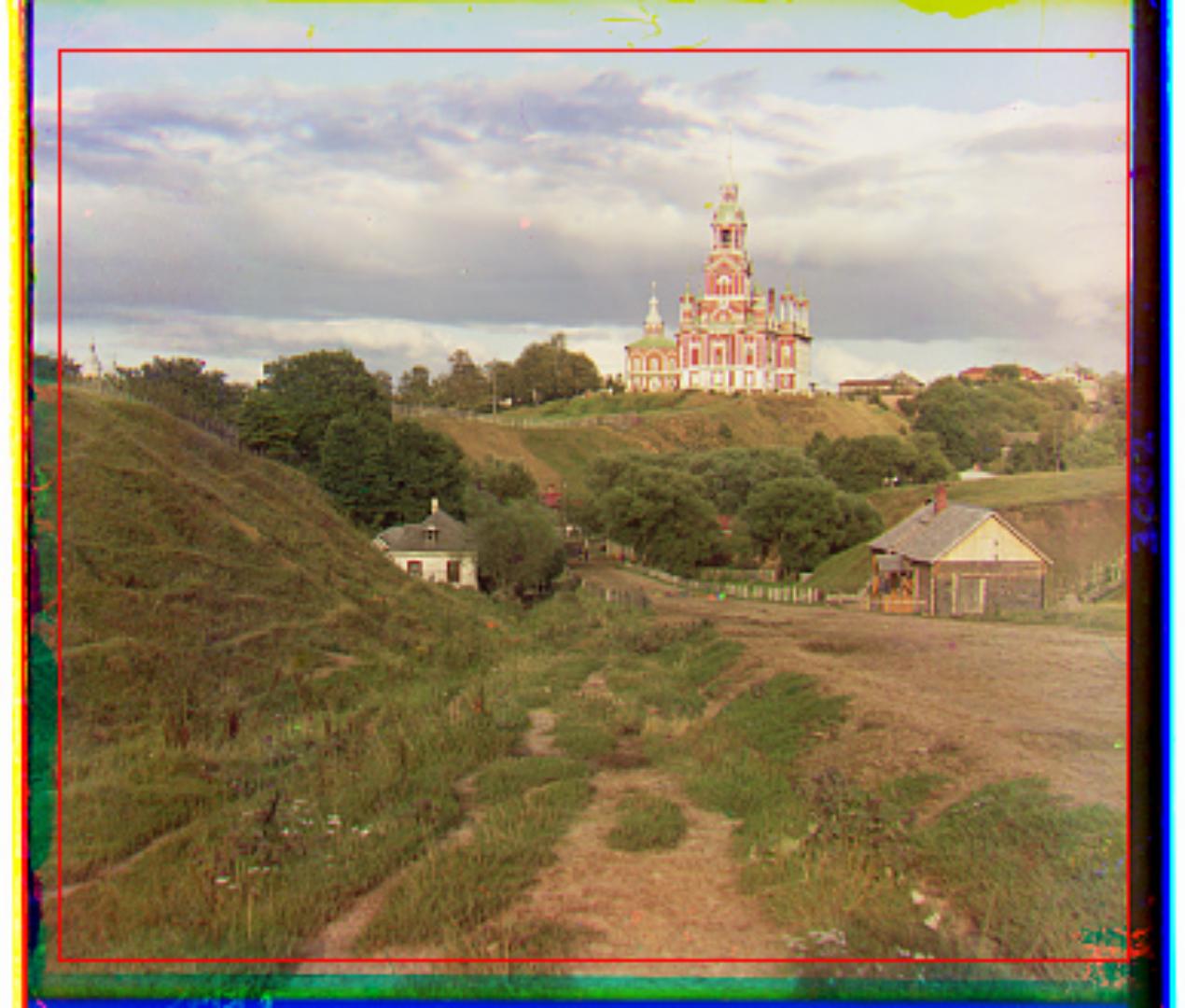
After Cropping
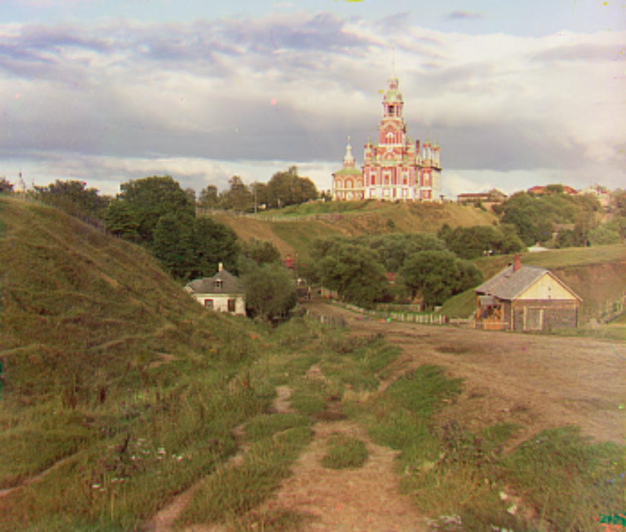
Cropped Region
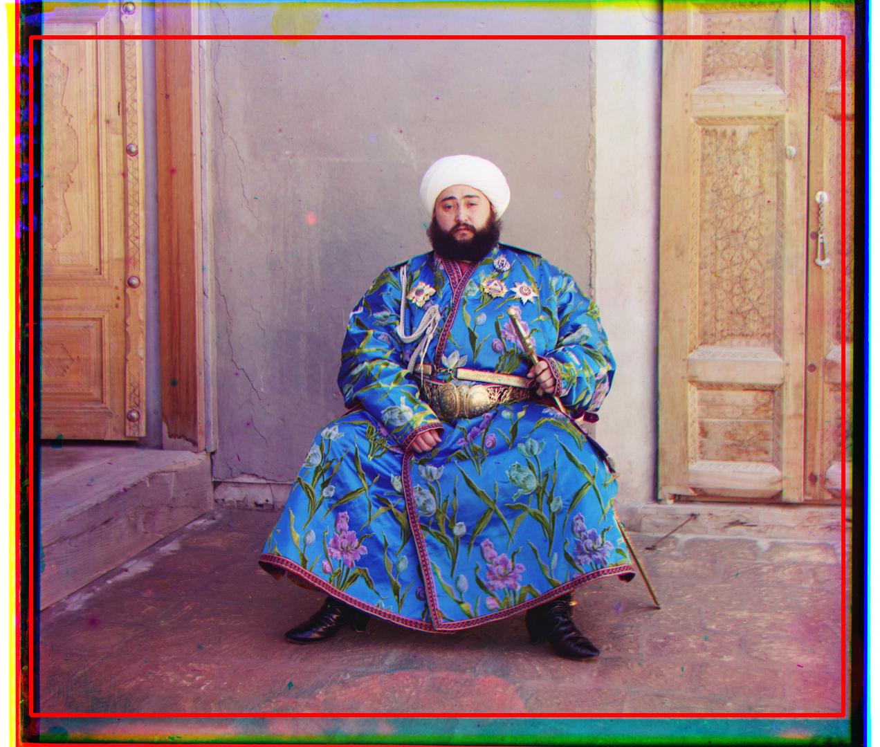
After Cropping
Cropped Region
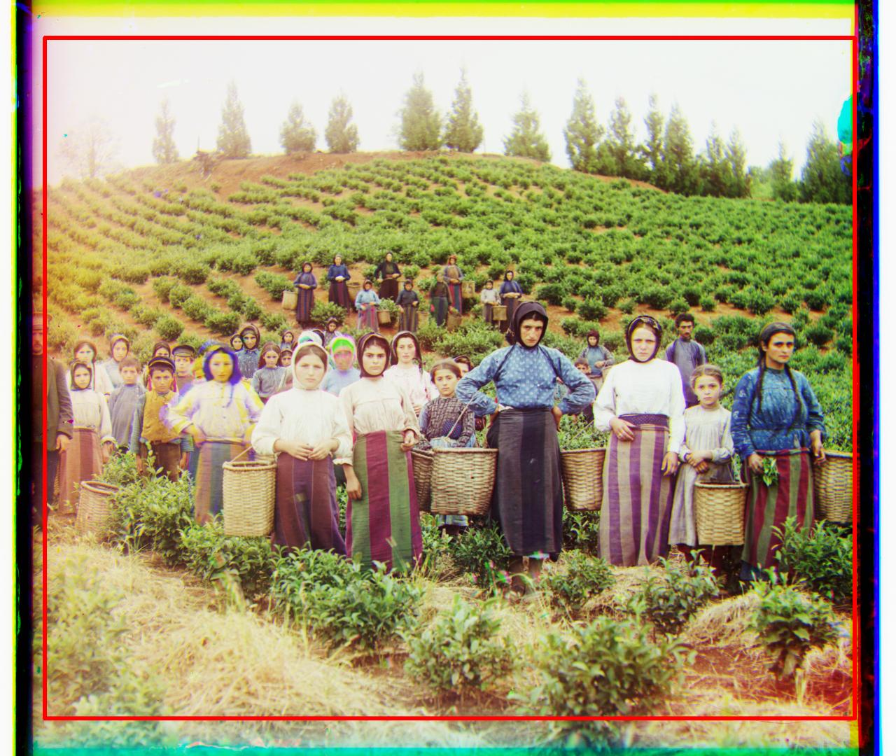
After Cropping
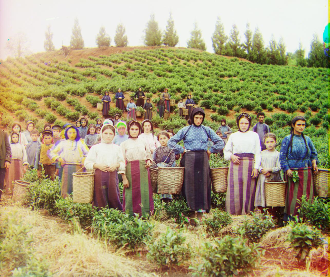
Cropped Region
After Cropping
Cropped Region
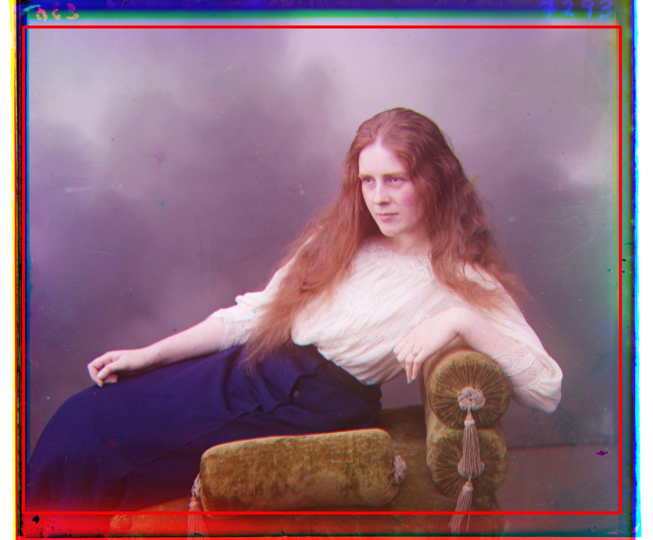
After Cropping
Cropped Region
After Cropping
Cropped Region
After Cropping
Cropped Region
After Cropping
Cropped Region
After Cropping
Cropped Region
After Cropping
Automatic Contrast Adjustment
In order to make the colors of the images more vibrant, an automatic contrast adjustment is performed.
Image contrasts can be tuned manually by adjusting the gain and bias parameters.
However, in automatic contrast adjustment, the gain and bias must be determined automatically.
Firstly, a histogram of pixel values are computed. This histogram is converted into a cumulative distribution function over [0,255].
Clipping off a small percentile (0.5%) of top and lower pixels, the maximum and minimum values are extracted.
With these values, the gain and bias parameters are computed:
- alpha = 255 / (max_value - min_value)
- beta = - min_value * alpha
Before Contrast Adjustment

After Contrast Adjustment
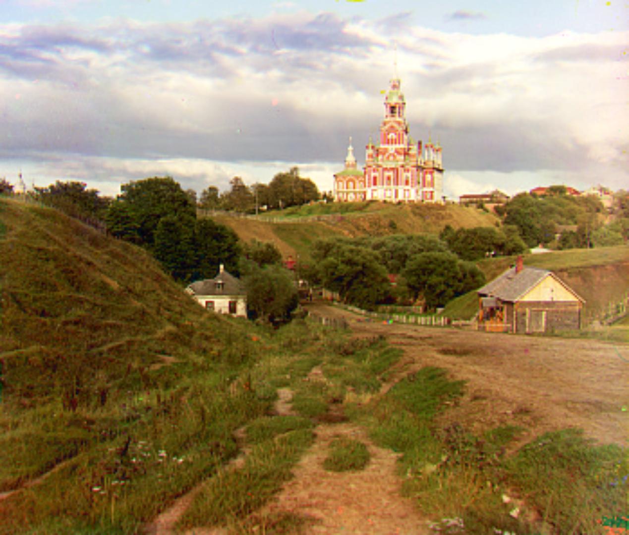
Before Contrast Adjustment

After Contrast Adjustment
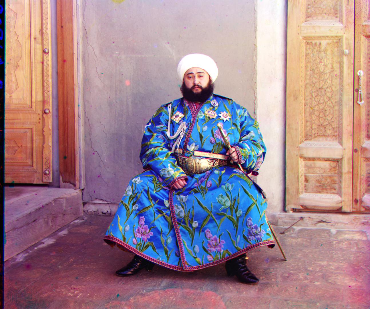
Before Contrast Adjustment

After Contrast Adjustment
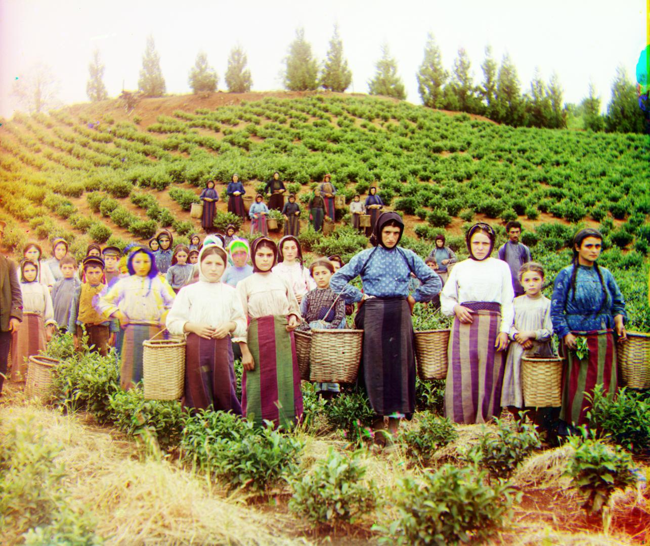
Before Contrast Adjustment
After Contrast Adjustment
Before Contrast Adjustment

After Contrast Adjustment
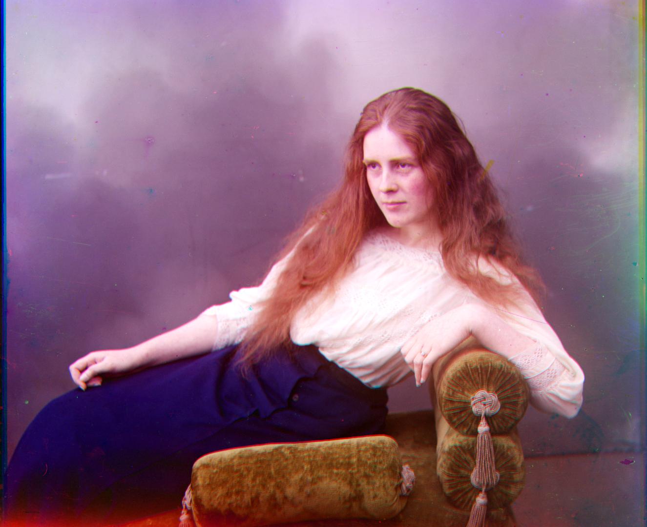
Before Contrast Adjustment

After Contrast Adjustment
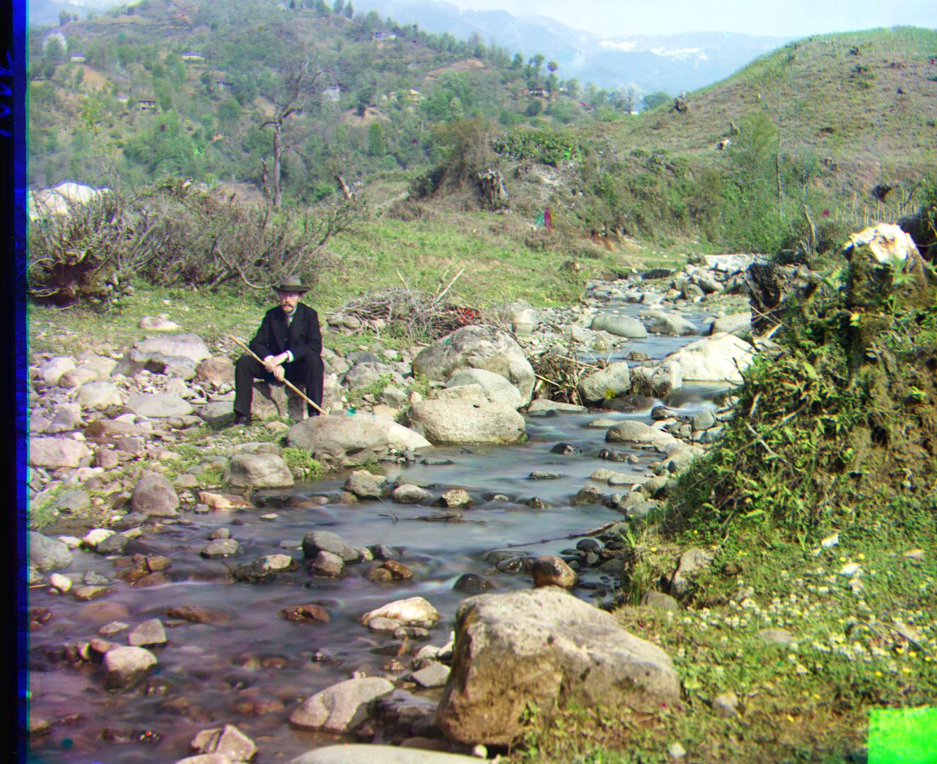
Before Contrast Adjustment

After Contrast Adjustment
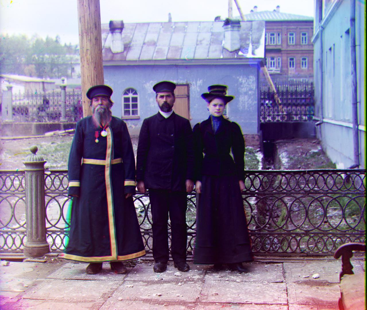
Before Contrast Adjustment

After Contrast Adjustment
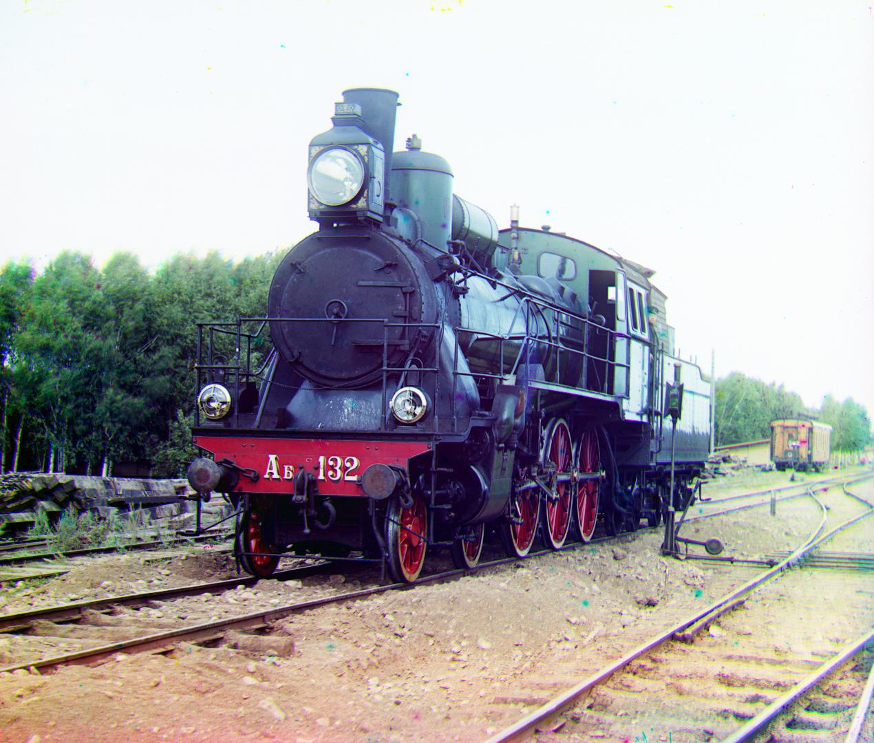
Before Contrast Adjustment

After Contrast Adjustment
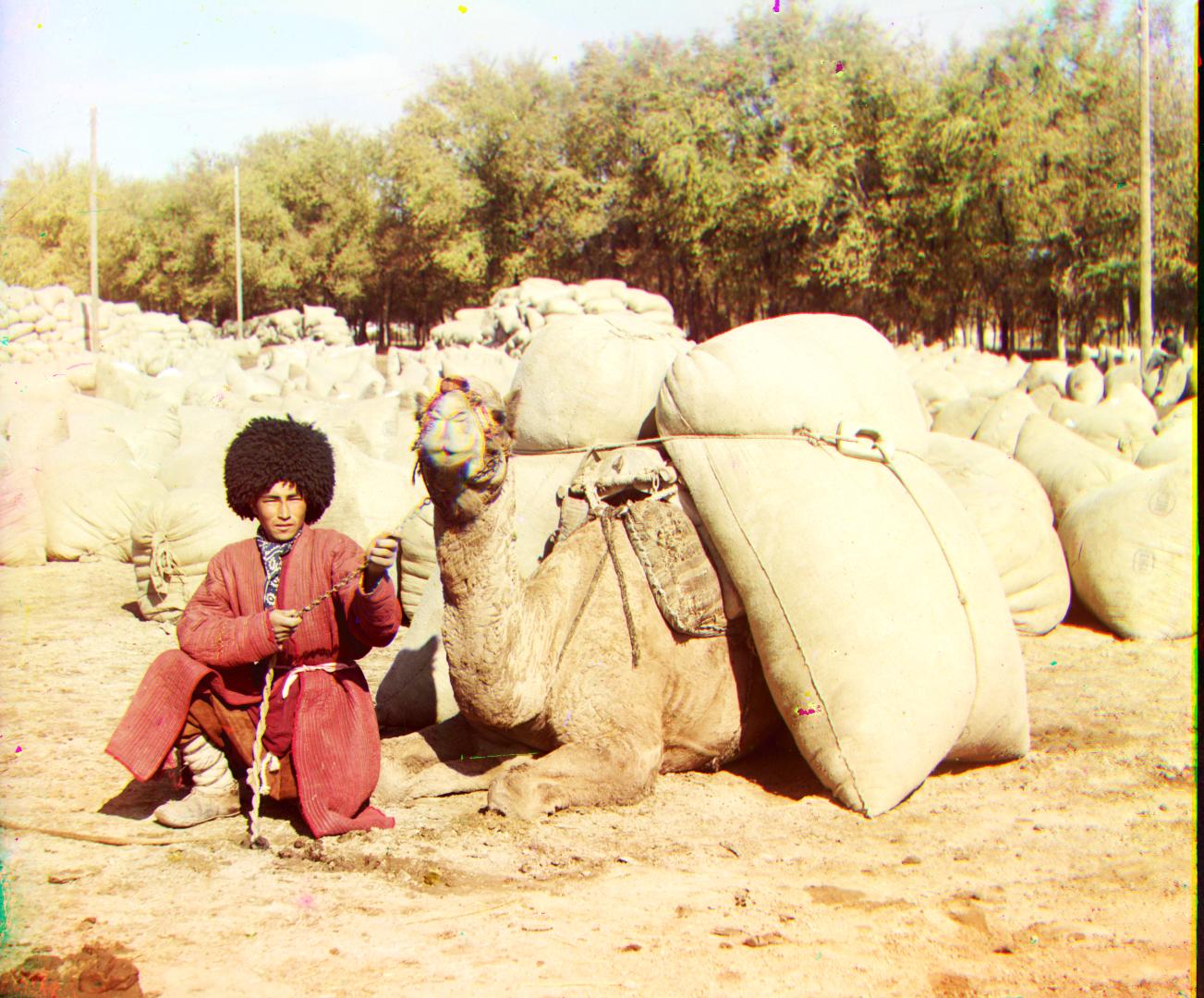
Before Contrast Adjustment

After Contrast Adjustment
